Hanwha SM481 PLUS Series Administrator’s Guide Eng.pdf.pdf - 第218页
7-60 Fast Flexible Placer SM481(L) PLUS Administ r ator’s Guide Memo Depth Z affects the pickup and placement height. 1: Nozzle 2: Pickup Surface of Part 3: Bottom Surface of Part 4: Placement Surface of Part Caution If …
7-59
Part Registration
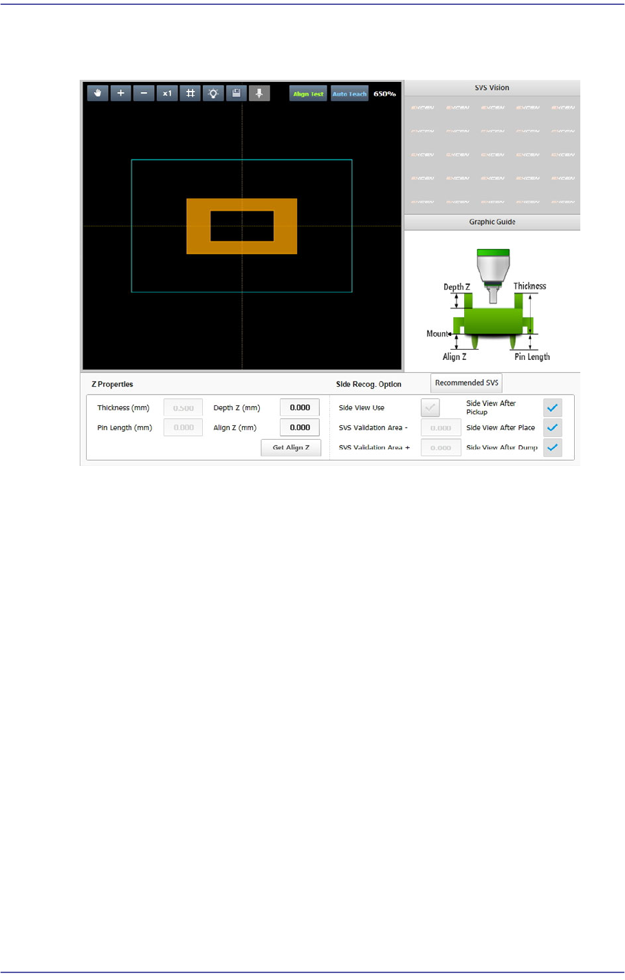
7.2.2.6. SETUP Z
Sets the data related to part height and SVS.
<SVS Vision> group
Enabled in the machine MMI. Displays the side image of the picked part viewed by
the SVS camera of the machine.
<Graphic Image> group
Describes the vision parameters related to height using graphic images.
<Z Properties> group
Sets the parameters related to part height.
<Thickness (mm)> edit box
Input the part height.
<Depth Z (mm)> edit box
Input the depth of the groove on top of the part. Unless there is a special purpose,
set the depth to “0”. For a part that cannot be picked up at its top surface, this
parameter must be set.
7-60
Fast Flexible Placer SM481(L) PLUS Administrator’s Guide
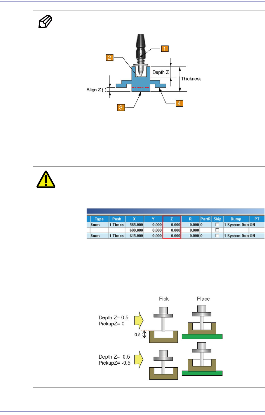
Memo Depth Z affects the pickup and placement height.
1: Nozzle
2: Pickup Surface of Part
3: Bottom Surface of Part
4: Placement Surface of Part
Caution If Depth Z is set, it is automatically reflected on the pickup
height (Pickup Z). Therefore, when Depth Z is set, do not
modify Pickup Z manually in the ‘Tape’ tab dialog box.
In the case of a part whose pickup height must be modified
such as a part supplied by the embossed tape, select
'General' of the Common Data of the part and select the
'Pickup Data' tab to modify the Z value. (Refer to the
<Pickup Data> tab in
“7.1. New Part Registration”
.)
<Pin Length> edit box

7-61
Part Registration
Inputs the pin length. Input the distance between the part bottom surface
contacting the PCB and the end of the pin.
<Recognition Height Z (mm)> edit box
Input the height for part recognition. When recognizing the upper side based on
the bottom surface, set the height to a minus (-) value, and when recognizing the
lower side, input the height to a plus (+)value.
<Get Align Z> button
When this button is clicked, the machine automatically measures the height at
which the part is recognized, and the measured value is entered in the
<Recognition Height Z> edit box.
<Side Recog. Option> group
<Side View Use> check button
Selected when checking for defective part pickup using a Side View Camera
(SVS).
For 0402 ~ 1608 chip parts, apply this function.
<SVS Validation Area -> edit box
Even though the value measured by the camera is slightly smaller than the height
(thickness) of the registered part, input the allowable range by which the currently
picked part is considered effective. The unit is in mm. Use the default set value.
If 0.05 is inputted while the height of the registered part is 0.2, when the part
height measured by the SVS camera is greater than 0.15 and less than 0.20, the
vision system considers that the currently picked part is effective.
<SVS Validation Area +> edit box
Even though the value measured by the camera is slightly greater than the height
(thickness) of the registered part, input the allowable range by which the currently
picked part is considered effective. The unit is in mm. Use the default set value.
<Side View After Pickup> Check box
Enabled when the <Side View Use> check button is selected. Selected in cases to
check for part pickup using the SVS camera after picking up a microchip.
<Side View After Place> Check box
Enabled when the <Side View Use> check button is selected. Selected in cases to
check for part placement using the SVS camera after placing a microchip.
<Side View After Dump> Check box
Enabled when the <Side View Use> check button is selected. Selected in cases to
check for part dumping using the SVS camera after dumping a microchip.4
<Recommend SVS> button
Applies the default value to all part parameters related to the SVS.