Hanwha SM481 PLUS Series Administrator’s Guide Eng.pdf.pdf - 第315页
12-7 LED placement Helps to specify t he optimum lighting value. The lighting is gradually changed automatically and the images are saved. The user can check the best image and identify the opt imum lighting value. Pleas…
12-6
Fast Flexible Placer SM481(L) Administrator’s Guide
: NG –Considered to be picked up upside down.
Caution The corresponding function can be used only for a bowl
feeder. When supplying parts using a bowl feeder, this
function must be selected.
<Load default data> button
Shows examples for inputting an LED mark, and indicates the default value
saved in the system regardless of the part actually picked up.
This function is a guide for inputting certain types of value. Since this data has
nothing to do with the part to be actually placed, use the data for reference
only.
In addition, when it is desired to return all values inputted back to the default
value, this function can be used.
It is possible to judge whether inputted values for ‘Area 1’ and ‘Area 2’ are
appropriate by clicking the <Outline> button.
Whether to recognize the polarity must be checked by clicking the <Test> button.
If the recognition result is ‘OK’, when the <Test> button is clicked again, with the
part being turned 180° manually using the jog box, check whether the recognition
result is ‘NG’.
If the setup has been performed properly, click the <Close> button to save the set
value.
<Use Chip R flip auto check>
This is used only in the Part Edit Screen for Chip R part. It is selected to use the
function that checks the turnover of the Chip R part.
(Chip-R3216, Chip-R2012, Chip-R1608, Chip-R1005, Chip-R0603, Chip-R0402 etc.)
<Move> button
Tests component recognition by using the set align data. Please refer to“7.1.1
Common Align Data” for more information.
<Test> button
Tests component recognition by using the set align data. Please refer to“7.1.1
Common Align Data” for more information.
<Image Capture> button
12-7
LED placement
Helps to specify the optimum lighting value. The lighting is gradually changed
automatically and the images are saved. The user can check the best image and
identify the optimum lighting value. Please refer to“7.1.1 Common Align Data” for
more information.
<Auto Teach> button
Automatically finds out the component align data. For more details, refer the “<Use
LED flip check>Check Box”of“7.1.1 Common Align Data” for more information.
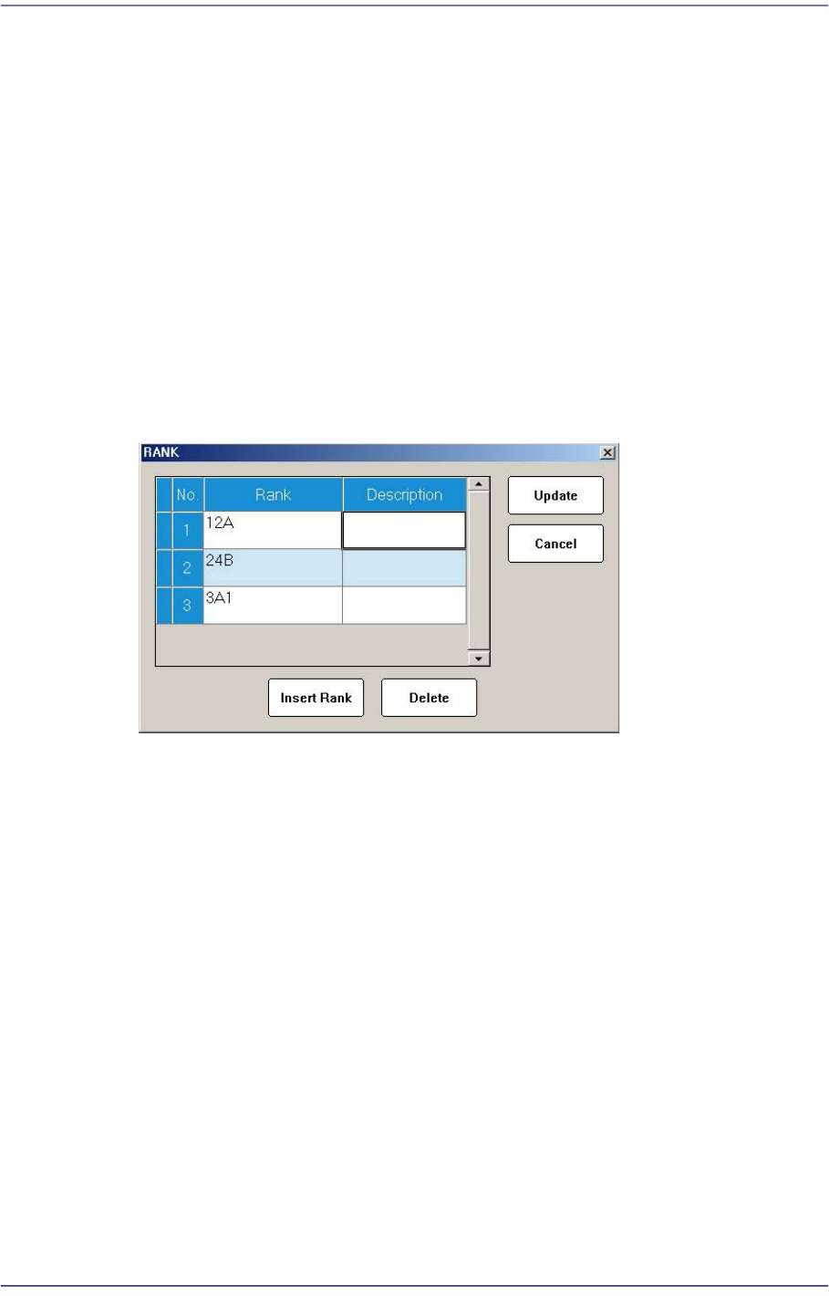
<Rank> buttion
When placing a part whose shape is identical but characteristics including brightness
are different, the rank function registers only one part and sets its rank differently to
allow parts to be placed efficiently. However, the part recognition data must be
completely identical. Up to two ranks can be set and used.
Clicking this button will display the following dialog box for setting the Rank.
<Insert Rank> button
A grid is added on the screen so that the rank can be newly added.
<Delete> button
The selected rank is deleted.
<Update> button
Saves the changed rank information and closes the window.
<Cancel> button
Closes the window without saving the changed rank information.
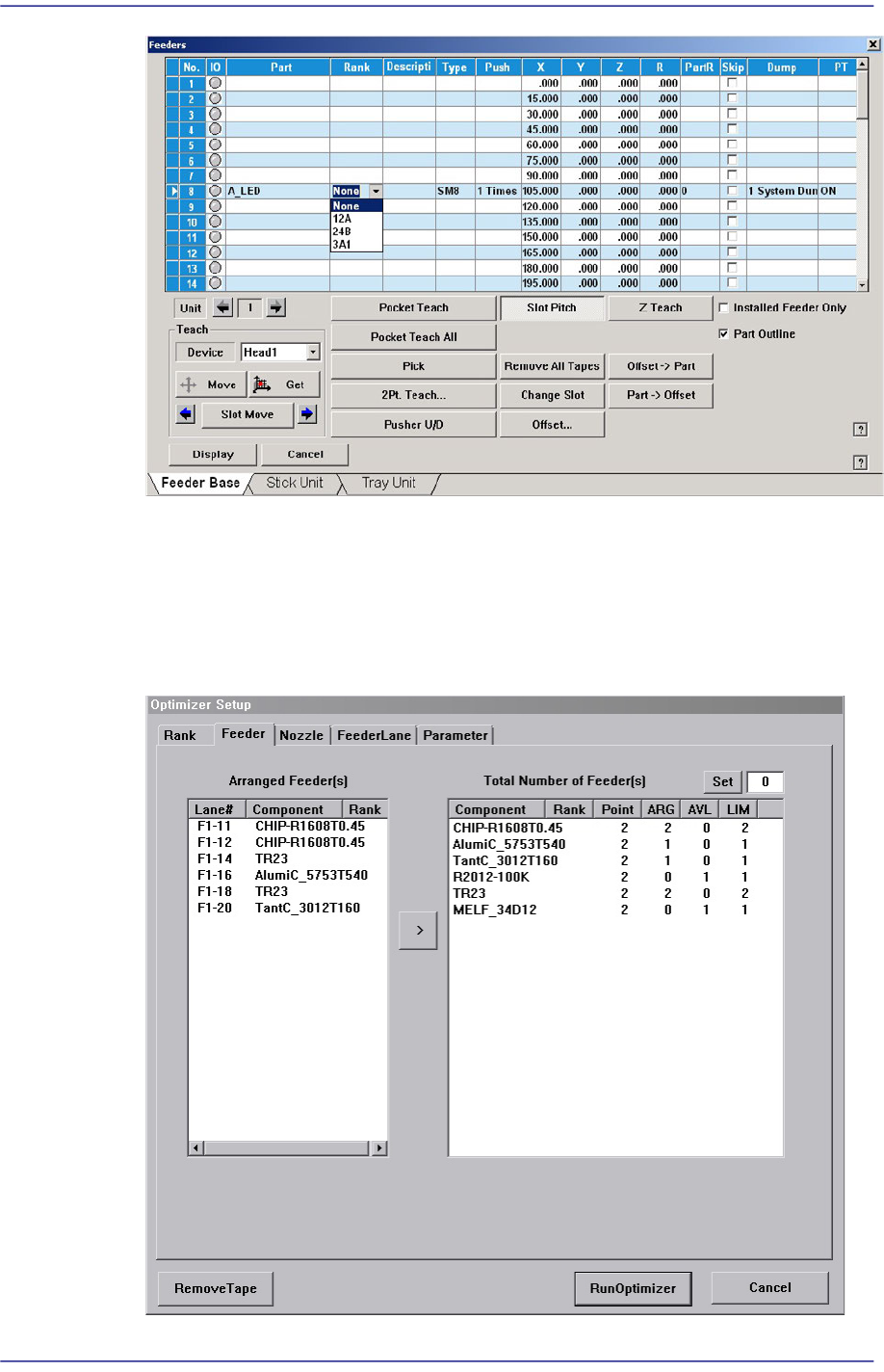
When the rank has been registered, the corresponding rank can be checked by
selecting the rank from the “Feeders” dialog box as shown in the following figure.
For ITS equipment, the operator must check the rank before performing work. For
general equipment, the operator can check the rank visually.
12-8
Fast Flexible Placer SM481(L) Administrator’s Guide
When using the rank function, even though parts are identical, they are treated as
different parts according to their rank. Therefore, when registering placement point
using “Steps” dialog box, the user must set up part name as well as the feeder that uses
the part of corresponding rank. In addition, when using the optimization program, the
user must separately set up the feeder of the corresponding before performing
optimization.