Hanwha SM481 PLUS Series Administrator’s Guide Eng.pdf.pdf - 第24页
Fast Flexible Placer SM481(L) PLUS Administ r ator’s Guide x Warning If the safety sensor of the do or is canceled arbitrarily, the machine will not stop even though th e door is opened during operation, which coul d cau…
Preface
ix
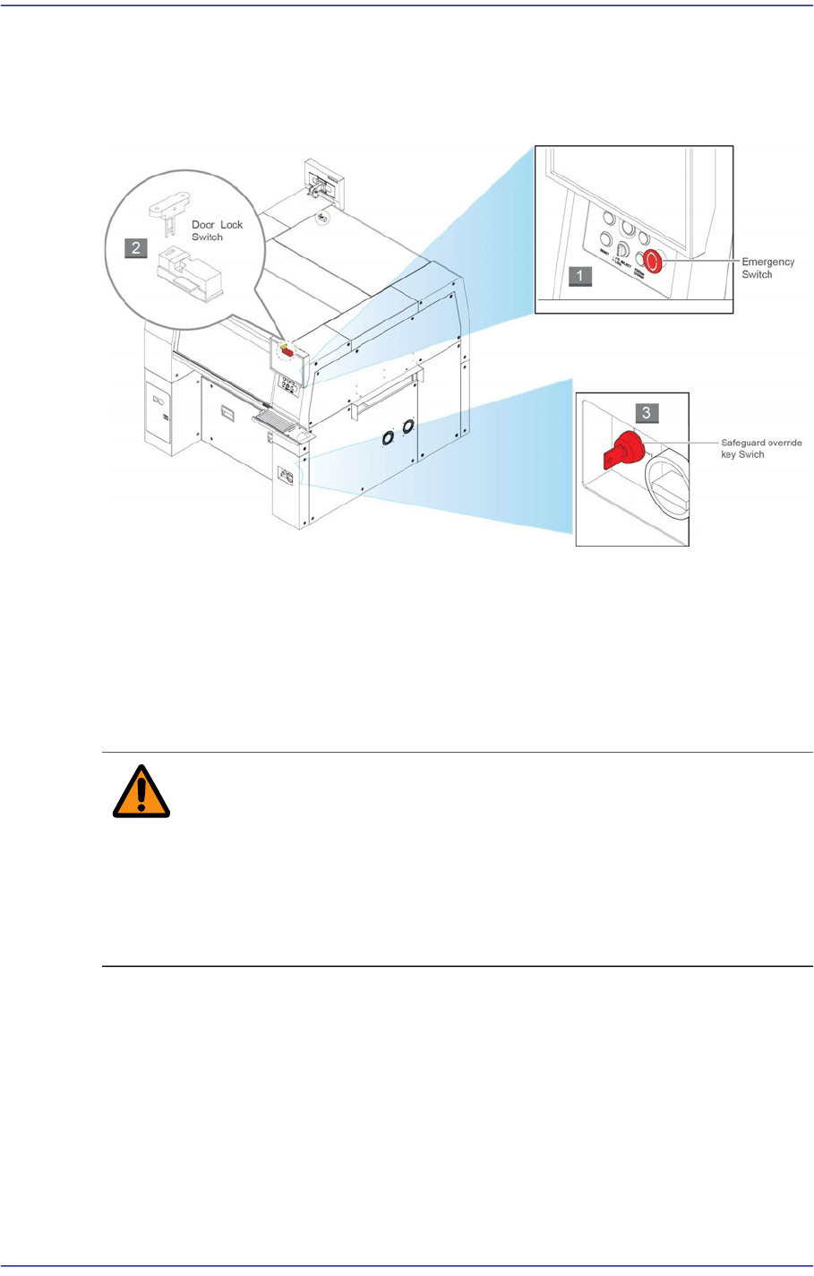
Operation of the safety interlock
This section describes the operation of safety interlocks manipulated to stop the machine
immediately under an emergency situation or for maintenance purposes.
1) EMG (Emergency Stop) switch
This is an emergency stop switch. Operation of this machine is immediately suspended
if this switch is pressed in case of an emergency.
Supply of all powers except for the power to a computer is ceased. The emergency
stop status can be released by turning the ‘EMG’ switch in the direction of the arrow
and pressing the RESET Button.
Warning When the emergency shutdown has been applied, the
power supply to all of the machine’s servo motors is turned
off. However, the power supply to other components and
devices remains turned on. Exercise care when taking
measures against an error for the section to which power is
supplied.
2) Door Lock switch
If the door is open while this machine is running, the door switch is activated and the
system comes into the emergency stop status. The emergency stop status is released if
the door is closed. In order to resume the operation, press ‘READ’ Button on the
operation panel to release the emergency status, then press ‘Start’ Button.

Fast Flexible Placer SM481(L) PLUS Administrator’s Guide
x
Warning If the safety sensor of the door is canceled arbitrarily, the
machine will not stop even though the door is opened
during operation, which could cause injury. The safety
sensor of the door must not be canceled arbitrarily.
Specifications of Machine
Applicable component sizes
Flying vision recognition system
The sizes of components applicable to this machine are prescribed in the following table,
and is applicable to general components usage as well.

Preface
xi
Tablei.1Applicable Component Sizes (vision recognition system)
The placement Speed
The following data concerns the speed of placement for each part. The actual cycle time
can vary depending on the size of PCB, frequency of the nozzle replacement, etc.
Components
Flying vision
MEGA FOV 16
mm
Chips
0402 ~ □16mm
IC, Connector
Less than □16mm, Lead
Pitch: More than 0.4 mm
BGA, CSP
Less than □16mm, Ball
Pitch: More than 0.4mm
Upward vision
MEGA FOV 35
mm
IC, Connector
Less than □16 mm, Lead
pitch: More than 0.3 mm
Less than □32 mm, Lead
pitch: More than 0.4 mm
BGA, CSP
Less than □16 mm, Ball
pitch: More than 0.4 mm
Less than □32 mm, Ball
pitch: More than 0.5 mm
Upward vision
MEGA F
OV 45
mm
IC, Connector
Less than □32 mm, Lead
pitch: More than 0.4 mm
Less than □42 mm, Lead
pitch: More than 0.5 mm
BGA, CSP
Less than □16 mm, Ball
pitch: More than 0.4 mm
Less than □32 mm, Ball
pitch: More than 0.5 mm
Less than □42 mm, Ball
pitch: More than 1.0 mm
Maximum Height
Flying vision 10 mm
Upward vision 15 mm