Hanwha SM481 PLUS Series Administrator’s Guide Eng.pdf.pdf - 第116页
6-6 Fast Flexible Placer SM481(L) PLUS Administ r ator’s Guide <Light> button Sets the lighting for the fiducia l camera. When t his Button is clicked on, the following dialog box is displayed. Combo Box Used f…
6-5
Board Definition
<Origin X> edit box
Set the X value of the placement origin of PCB.
<Origin Y> edit box
Set the Y value of the placement origin of PCB. Click on <Origin X> or <Origin
Y>, then click on the “Move” or “'Get” Button in the <8. Teach> group, Teaching
of placement origin is possible based on the selected object from the Combo Box.
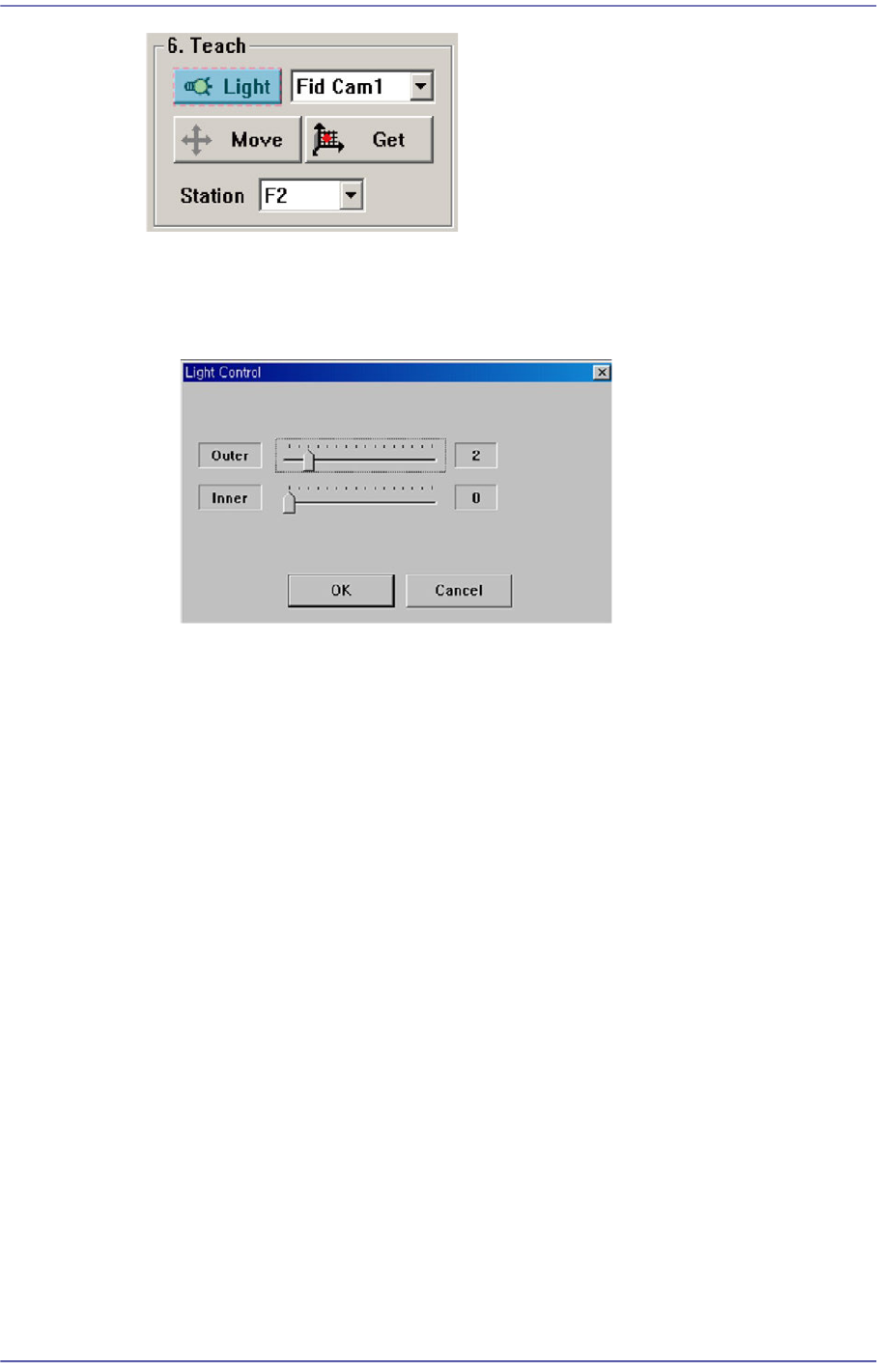
<6. Teach> group
Used for moving the selected object from the Combo Box to the position of assigned
coordinates, or for obtaining the present coordinates by rotating the XY, Z axis driving
motor.
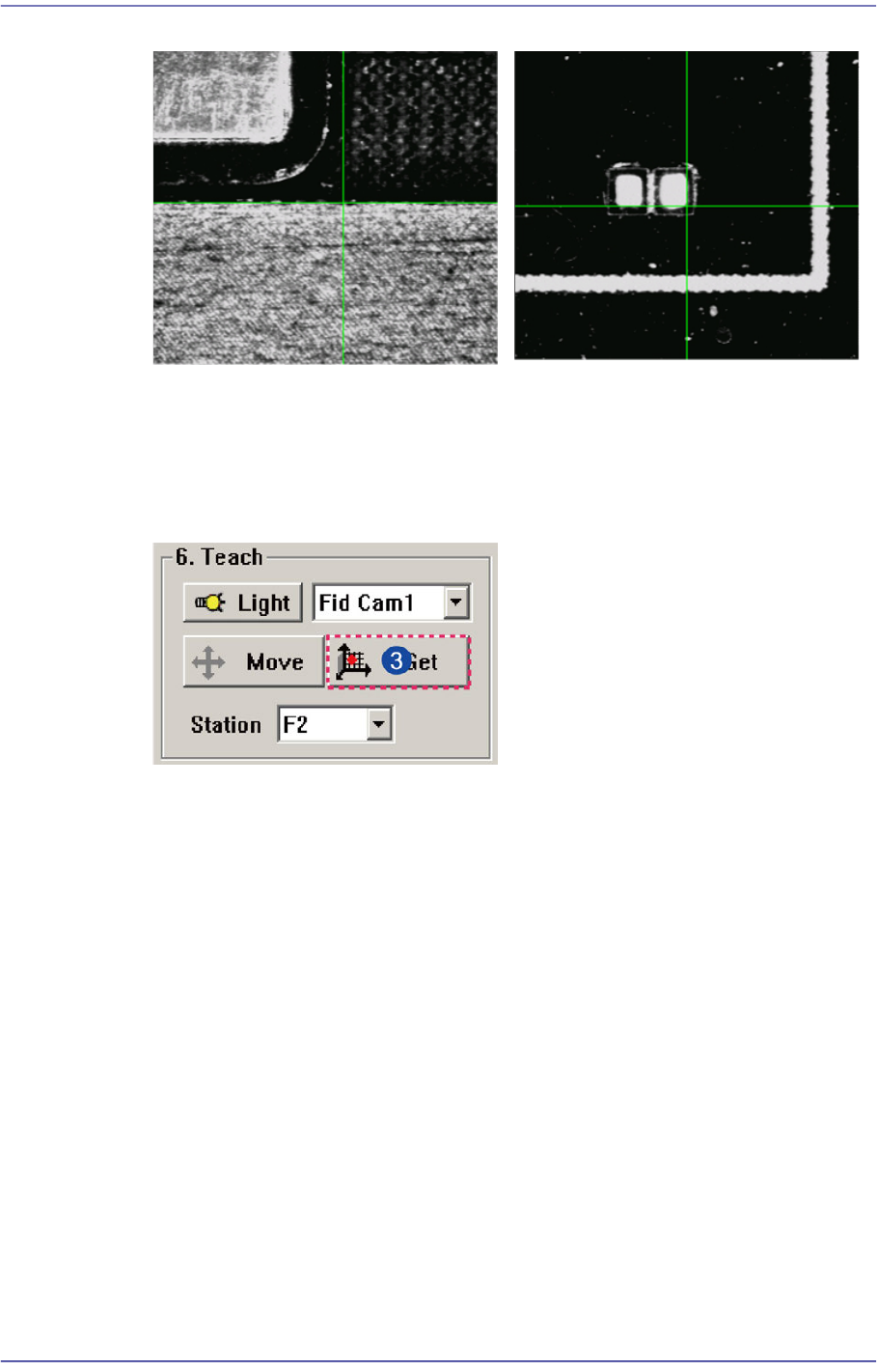
[Case 1 - Using the Board Stop]
It is difficult to apply to the array PCB
since it is not easy to check the
coordinate.
[Case 2 - Utilizing a pattern in the
PCB]
Utilize the pattern in the PCB and
apply it to the array PCB since it is
easy to check the coordinate.
6-6
Fast Flexible Placer SM481(L) PLUS Administrator’s Guide
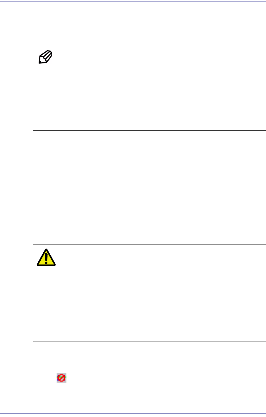
<Light> button
Sets the lighting for the fiducial camera. When this Button is clicked on, the
following dialog box is displayed.
Combo Box
Used for selecting the object to move to the designated coordinates by rotating the
XY, Z axis driving motor or to select the object for which the present coordinates
is searching. Selectable objects are as follows;
Fid Cam2: Select the fiducial camera on the front gantry.
Head 1 ~ Head 10: Select #1 ~ #10 heads.
<Move> button
Move the object selected in the Combo Box to the position of the assigned
coordinates. Before clicking on the <Move> button, the objects (Place Origin,
Move Z) related with the coordinates must first be clicked with the mouse.
<Get> button
Obtain coordinates for XY, Z axis with reference to the object selected in the
Combo Box. At this time, the objects (Place Origin, Move Z) related with
coordinates must first be clicked with the mouse before clicking on the <Get>
button.
<7. Board Size> group
Set the board size.
<X> edit box
Set the length of PCB size.
<Y> edit box
6-7
Board Definition
Set the width of PCB size.
<Conv.Width > button
Adjust the conveyor width according to the set width of the PCB.
Memo The sizes of PCB applicable for this machine are as follows.
Max.
510L×460W×4.2H [ mm ] - Single Lane/ Long Conveyor
460L×250W×4.2H [ mm ] – Dual Lane
Min.
50L×40W×0.38H [mm]
<8. Handling> group
Set the data necessary for PCB operation.
<Move Z>
After the part is picked up, set the head moving height with the surface of the PCB
being “0” when moving the head.
The default value is 4mm. However, if the placed part height is higher than 4mm,
input the height part in mm unit when it is placed on the PCB.
The height cannot be set to a value less than 4 mm. The height can be inputted up
to 12 mm. As this value becomes greater, the working time becomes longer.
Therefore, set the height to optimum value.
Caution Move Z is installation height, the test PCB shall not hang
down.
If teaching is done without checking whether a nozzle is
mounted on the Head,
the minimum movement height of head becomes low and
the head and the transport rail might collide.
Since the Z axis moving height is different for each
machine, the same value cannot be set for all machines.
<Fix Type> combo box
Select the method for fixing a PCB.
Default: A method of fixing the PCB by moving up backup table.