Hanwha SM481 PLUS Series Administrator’s Guide Eng.pdf.pdf - 第321页
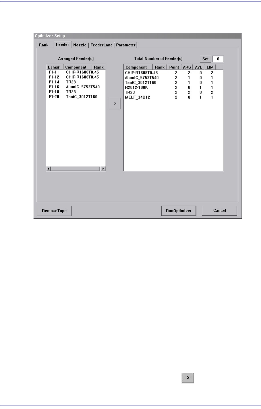
12-13 LED placement 12.4.2. Feeder Figure12.4 “Opt imizer Setup: Feeder Arrangement” dialog box A window to set the optimum ar rangement of tape feeders. Optimizer can arran g e T ape feeders on the optimum feeder lanes …
12-12
Fast Flexible Placer SM481(L) Administrator’s Guide
Refers to bar type lighting boards. When working on LEDs of the same rank,
select this type.
<Bar-Feeder Matching> check box
In the case of bar type lighting boards, select this check box when receiving parts
from one feeder for all placement points in one line.
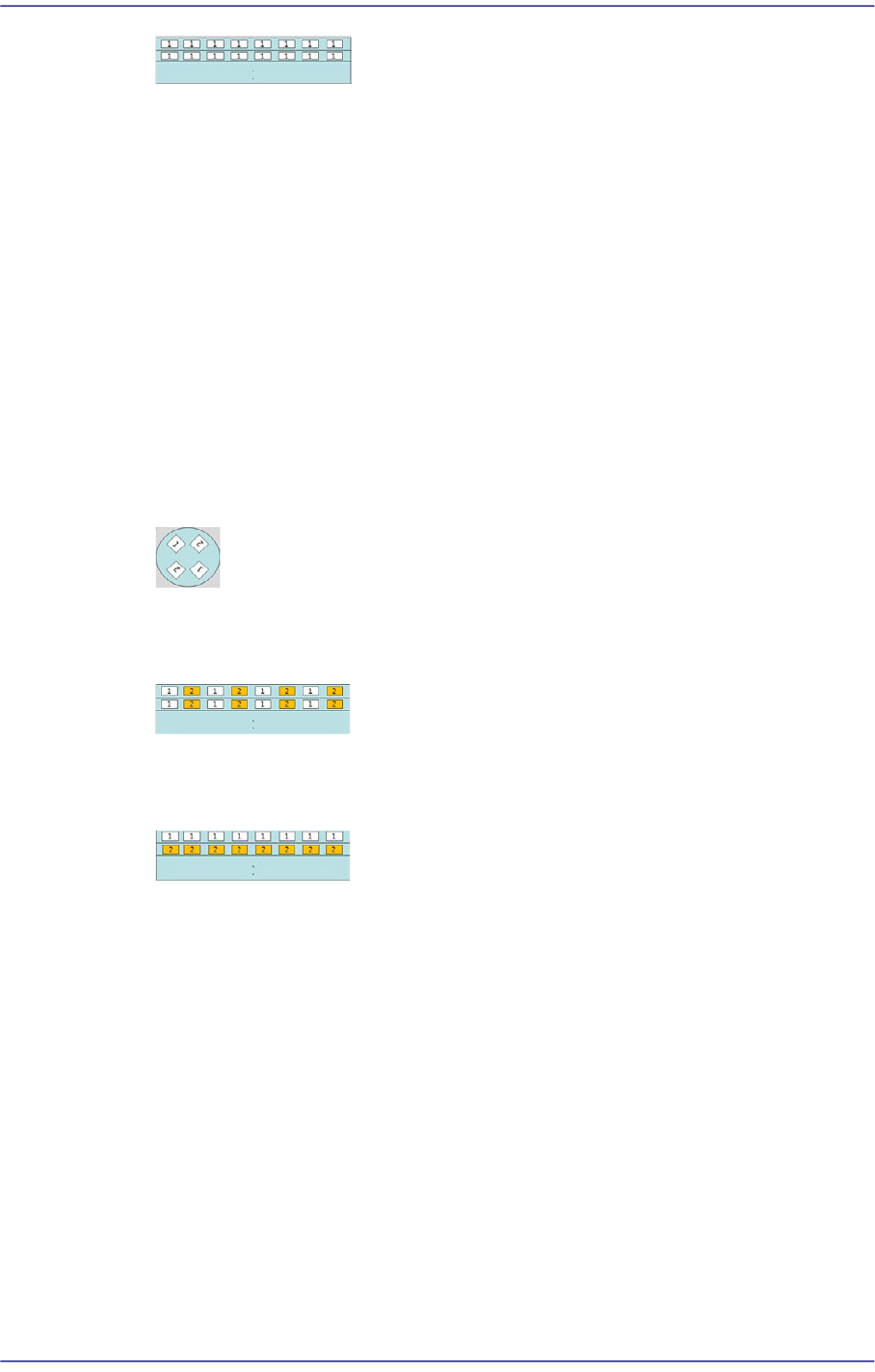
<Use 2 Rank> group
Refers to the method to perform work on the PCB using two types of LED of different
rank.
<1st Rank> Combo box
The 1st rank refers to the part with the rank to be placed first. That is, select the
part with the rank to be placed first. The part corresponding to the number ‘1’ in
the figure is the one with the 1st rank.
Refers to the round lighting board. Select this type when performing work with
LEDs of the same rank facing each other.
Refers to bar type lighting boards. Select this type when performing work on
LEDs of different rank in one line.
Refers to bar type lighting boards. Select this type when working on LEDs of the
same rank by line.
<User Defined> option button
Refers to the existing setup option. Select this setup when performing work on general
PCBs other than PCBs for LED lighting. At this time, for the part selected from the
<1st Rank> combo box, the rank order is set to ‘1’ and another one to ‘2’. The rank
order of the other part that is not set will be set to ‘0’
<Feeder Count Per Rank> combo box
Sets the number of tape feeders to be arranged for a rank. It is possible to arrange up to
9 feeders.
12-13
LED placement
12.4.2. Feeder
Figure12.4 “Optimizer Setup: Feeder Arrangement” dialog box
A window to set the optimum arrangement of tape feeders. Optimizer can arrange Tape
feeders on the optimum feeder lanes automatically in consideration of simultaneous
pickup and operation time. However, the user must specify mounting positions for Tray
Feeders and Stick Feeders.
<Arranged Feeder(s)> list box
<FDLane> column
The number in []is the feeder base number. The feeder lane number with F in front
is Front Feeder Base and that with R in front is Rear Feeder Base.
<Component> column
Displays the component name of the tape feeder mounted on the corresponding
lane. This list displays already arranged feeders. As these feeders are not arranged
arbitrarily by Optimizer, they affect arrangement of other feeders by Optimizer.
In other words, if there are feeders already arranged, the Optimizer arranges other
feeders to increase simultaneous pickups in consideration of these.
For the tape feeders of those indicated here, which are desired to be arranged
optimally by the optimizer, click the arrow button ( ) to move then to the right
list box and execute the optimizer.

12-14
Fast Flexible Placer SM481(L) Administrator’s Guide
All arranged tape feeders can be removed by pressing the <Remove Tape> button
under the dialog box..
<Total Number of Feeder(s)> list box
For each feeder, the number of placement points, the number of arranged tape feeders,
and the number of tape feeders to be newly arranged are displayed in the list box on
the right and can be viewed at a glance.
<Component> column
The components to be supplied from tape feeders are all displayed here.
<Point> column
Displays the number of placement points for each component. This can be referred
to when deciding the number of feeders to be mounted.
<ARG> column
Displays the number of feeders already arranged on the feeder lane for each
component. This number coincides with the number of feeder lanes shown in the
list box on the right.
<AVL> column
Displays the number of feeders to be arranged by Optimizer for each component.
<LIM> column
Displays the sum of the feeders shown in ARG and AVL for each component. In
other words, it is the limited number of feeders that can be arranged for each
component. The minimum value is 1.
<Set> button
Used to specify the number of feeders to be arranged for each component. When there
is one feeder already arranged for a certain part, enter ‘3’ in the right edit box and click
this button. Then the number of <AVL> column becomes ‘2’.
Appropriate number of feeders must be set in consideration of the number of
placement points for each component. If the Optimizer considers that more than one
feeders are not necessary, it might not be used. .
To obtain good operation efficiency, a relatively large number of feeders must be
assigned to a component with many placement points.
button
Used to have the feeder selected in the <Arranged Feeders> list box to be arranged
again by Optimizer.