Hanwha SM481 PLUS Series Administrator’s Guide Eng.pdf.pdf - 第341页
13-11 Production Setu p <Mode> combo box Camera Selected when looking at the image of a specific camera. Select the corresponding camera from the <Device > combo box. Head Selected when looking at the i…
13-10
Fast Flexible Placer SM481(L) PLUS Administrator’s Guide
<Auto Skip Placements> check box
Even when a specific part has run short during automatic production, placement is
continuously performed on the remaining placement points, generating a warning
message.
Caution This function allows the placement to be simply performed
continuously. If interference is expected in the future
between the skipped part and the nearby placed parts while
performing placement, release this function.
<PCB Transfer Speed> combo box
Used to adjust the PCB feeding speed. When the PCB is heavy, if it is selected at too
high speed, the conveyor belt may not feed the PCB sufficiently with the belt rotating
while slipping. The default selection is Middle. Adjust the speed appropriately, if
necessary.
Fast: high speed
Middle: medium
Slow: low speed
<Speed> slide bar
Select the driving speed of the XY axis driving motor.
<Z Axis Mount Delay> slide bar
Works after adding the defined value in the slider bar to the placement delay value
setup in the common data at the time of part registration. This value is applied only to
Z-axis.
<Inhibit Lane> group
When it is not used, select the workstation. Then the PCB is not loaded on the
corresponding workstation.
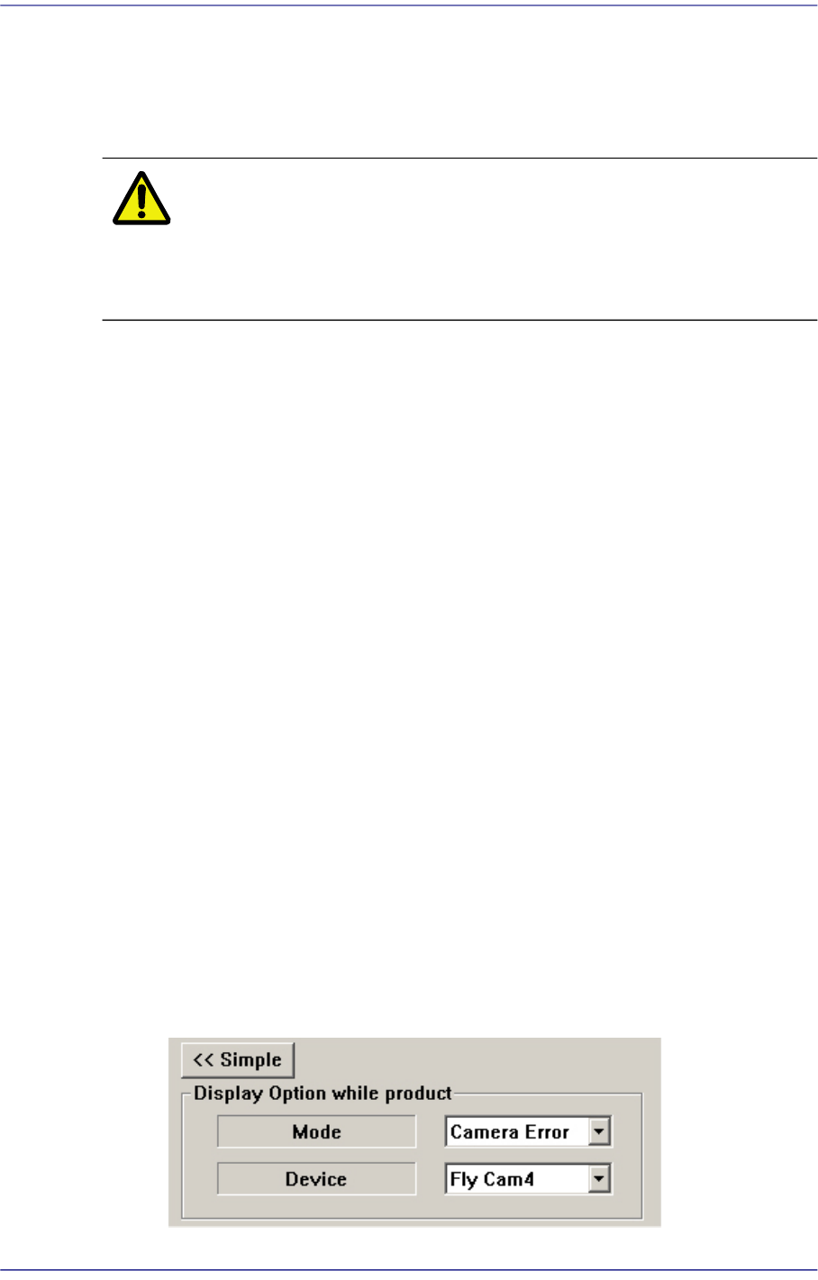
<Detail> button
<Display Option while product> group
This button is used to select the image viewed in the SMVision window during
PCB production.
13-11
Production Setup
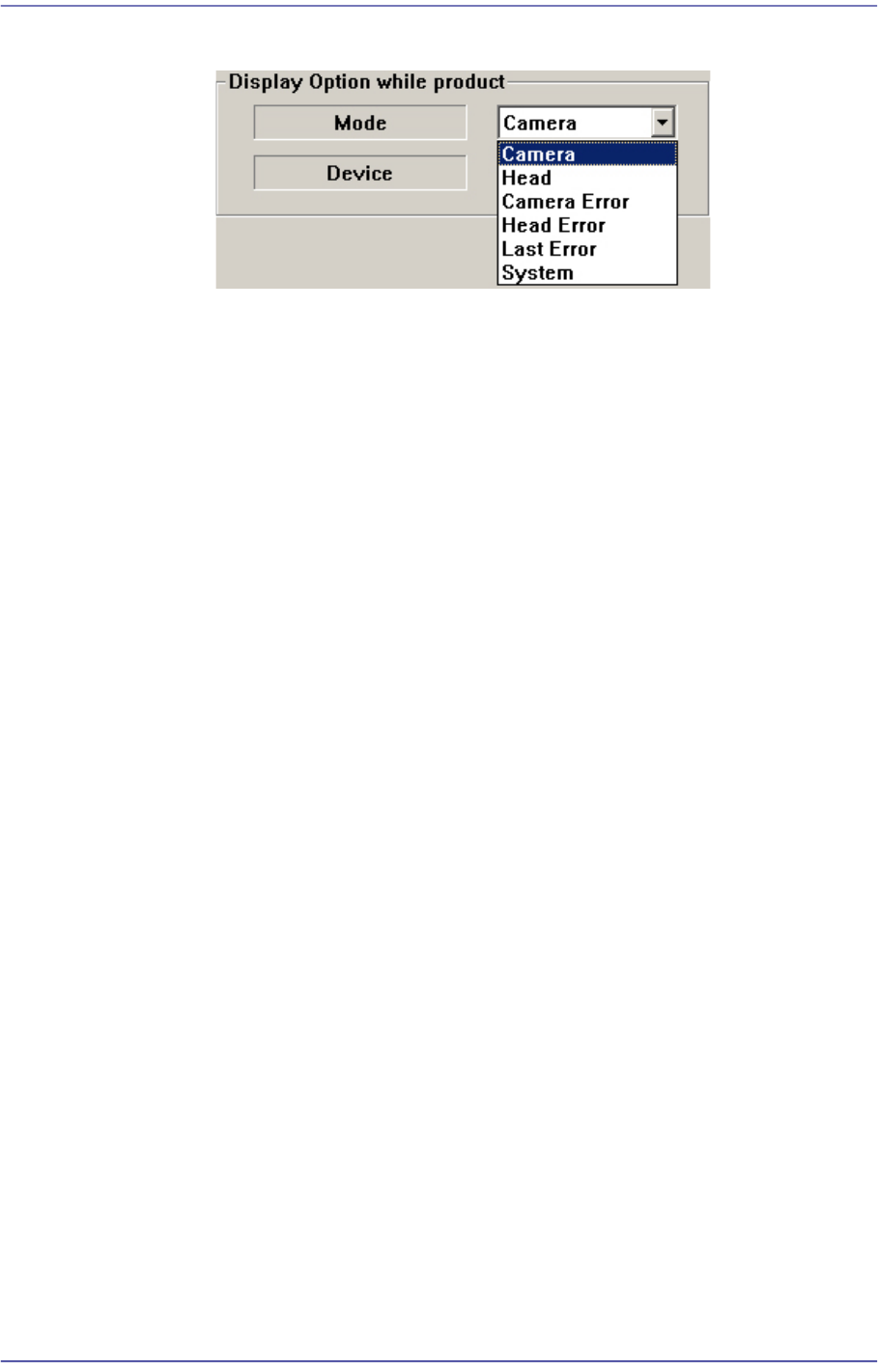
<Mode> combo box
Camera
Selected when looking at the image of a specific camera. Select the
corresponding camera from the <Device> combo box.
Head
Selected when looking at the image in which the part picked up by a
specific head is recognized. Select the corresponding head from the
<Device> combo box.
Camera Error
Selected when looking at the image of part recognition error from a
specific camera.
It shows the recognized part image according to the placement order
during placement. However, if the placement is completed, the camera
selected in the following <Device> combo box shows the part image error
that occurred last.
Head Error
Selected when looking at the recognition error image of part picked up by
a specific head.
It shows the recognized part image according to the placement order
during placement. However, if the placement is completed, it shows the
image of part recognition error that occurred last among the parts placed
by the head selected in the following <Device> combo box.
Last Error
It shows the recognized part image according to the placement order
during placement. However, if the placement is completed, it shows the
image of part recognition error that occurred last during placement.
System
Shows the part recognition image according to the placement order.
13-12
Fast Flexible Placer SM481(L) PLUS Administrator’s Guide
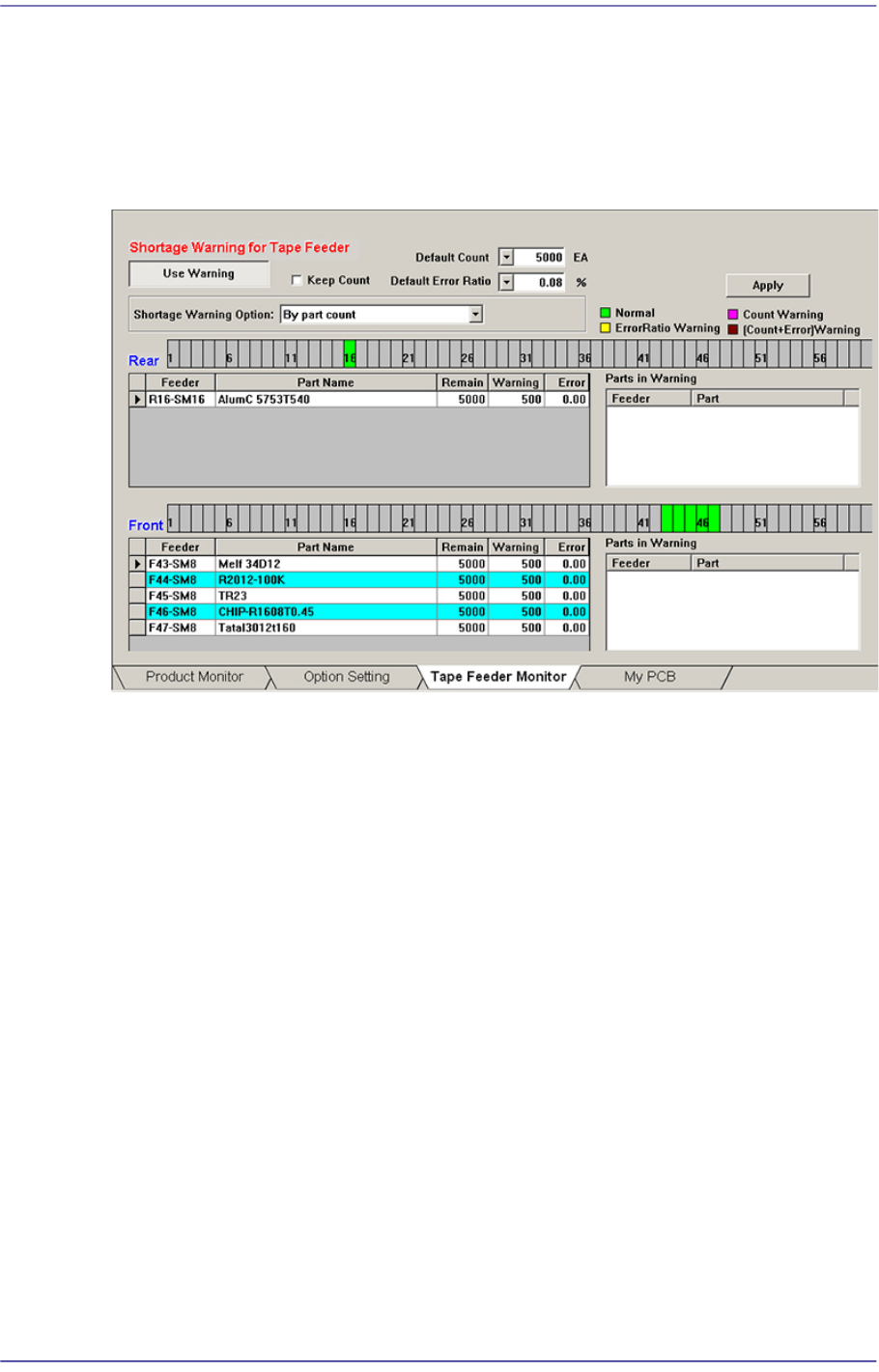
13.1.3. Tape Feeder Monitor
Sets the quantity of remaining components. It shows the remaining components of the
installed tape feeder and alarms against the component shortage. Able to monitor the
errors related with parts supply of tape feeder.
Figure13.5 “Tape Feeder Monitor” tab dialog
<Use Warning> button
Selects whether to automatically show the alarm message setup in the ‘Tape Feeder
Monitor’ tap dialog box while working. It is setup as ‘use’ in the above dialog box.
<Keep Count> check box
Generally, if the PCB program is downloaded, the remaining quantity is set up to the
default count.
In case the same PCB program must be downloaded again for a particular reason
during operation, select this check box to maintain the Remain Count of the tape
feeder installed already.
<Default Count> combo box
Indicates the part shortage alarm message box when the remaining quantity of parts
supplied to the tape feeder is less than the setup value.