Hanwha SM481 PLUS Series Administrator’s Guide Eng.pdf.pdf - 第25页
Preface xi Tablei.1Applicable Component Sizes (vision recognition system) The placement Speed The following data concerns the speed of placement for each part. The actual cycle time can vary depending on the size of PCB,…

Fast Flexible Placer SM481(L) PLUS Administrator’s Guide
x
Warning If the safety sensor of the door is canceled arbitrarily, the
machine will not stop even though the door is opened
during operation, which could cause injury. The safety
sensor of the door must not be canceled arbitrarily.
Specifications of Machine
Applicable component sizes
Flying vision recognition system
The sizes of components applicable to this machine are prescribed in the following table,
and is applicable to general components usage as well.

Preface
xi
Tablei.1Applicable Component Sizes (vision recognition system)
The placement Speed
The following data concerns the speed of placement for each part. The actual cycle time
can vary depending on the size of PCB, frequency of the nozzle replacement, etc.
Components
Flying vision
MEGA FOV 16
mm
Chips
0402 ~ □16mm
IC, Connector
Less than □16mm, Lead
Pitch: More than 0.4 mm
BGA, CSP
Less than □16mm, Ball
Pitch: More than 0.4mm
Upward vision
MEGA FOV 35
mm
IC, Connector
Less than □16 mm, Lead
pitch: More than 0.3 mm
Less than □32 mm, Lead
pitch: More than 0.4 mm
BGA, CSP
Less than □16 mm, Ball
pitch: More than 0.4 mm
Less than □32 mm, Ball
pitch: More than 0.5 mm
Upward vision
MEGA F
OV 45
mm
IC, Connector
Less than □32 mm, Lead
pitch: More than 0.4 mm
Less than □42 mm, Lead
pitch: More than 0.5 mm
BGA, CSP
Less than □16 mm, Ball
pitch: More than 0.4 mm
Less than □32 mm, Ball
pitch: More than 0.5 mm
Less than □42 mm, Ball
pitch: More than 1.0 mm
Maximum Height
Flying vision 10 mm
Upward vision 15 mm
Fast Flexible Placer SM481(L) PLUS Administrator’s Guide
xii
The pick and place cycle time
Tablei.2The pick and place speed
Memo In actual placement, the conditions that determine the cycle time may
vary depending on many factors such as the type of components, size
of PCB, placement position, etc. For more detailed information,
please contact our business department or the local agent.
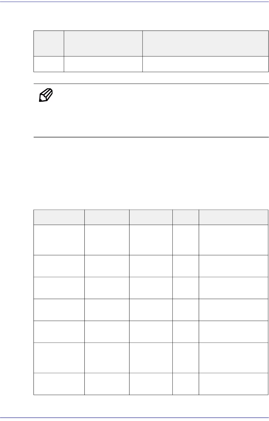
Placement Accuracy
The placement precision for applicable components type is shown in the following table,
and is applicable to general components usage as well.
The degree of placement may be different according to the composition of options for the
camera used for recognition of parts.
Classifi
cation
Speed Remarks
Chip
40,000 CPH(1608)
Simultaneous Pickup Standard Fly Vision
Classification XY R Cpk Remarks
Chip 0402 ± 0.04 mm ± 5.00 ° 1.0 Flying Vision MEGA
FOV24 mm, Mount
Offset
Chip 0603 ± 0.08 mm ± 5.00 ° 1.0 Flying Vision MEGA
FOV24 mm
Chip 1005 ± 0.10 mm ± 5.00 ° 1.0 Flying Vision MEGA
FOV24 mm
Lead IC 0.4
Pitch
± 0.05 mm ± 0.30 ° 1.0 Flying Vision MEGA
FOV24 mm
CSP Ball 0.4
Pitch
± 0.05 mm ± 0.30 ° 1.0 Flying Vision MEGA
FOV24 mm
QFP100 0.5 P ± 0.06 mm ± 0.30 ° 1.0 Upward
Vision(FOV35mm,
FOV45mm)
QFP168 0.3 P ± 0.03 mm ± 0.30 ° 1.0 Upward Vision(Mega-
FOV35mm)