Hanwha SM481 PLUS Series Administrator’s Guide Eng.pdf.pdf - 第97页
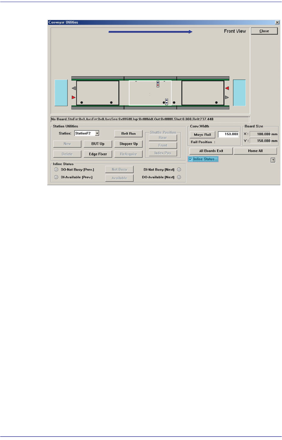
4-15 Tools Shortcut M enu Figure4.5 “Conveyor System -Inline Status” dialog box <Inline Status> group Can handle SMEMA related output manually and display the input status (lig ht on-On, light off- Off). DO-Not…

4-14
Fast Flexible Placer SM481(L) PLUS Administrator’s Guide
<Station Utilities> group
<Station> combo box
Select the current conveyor station. (StationF1, StationF2, StationF3)
<BUT Up/Down> button
When ‘StationF2’ or ‘StationR2’ is selected in the <Station> combo box, Up/
Down of the backup table is performed.
<Stopper Up/Down> button
Moves up/down the Stopper.
<Edge Fixer> button
When ‘StationF2’ or ‘StationR2’ is selected in the <Station> combo box, performs
operation of edge fixer.
<ReAcquire> button
This is the function used for testing.
<Belt Run> button
Operates the driving belt of selected station.
<New> button
This function is enabled only for the station from which PCBs are removed using
the <Delete> button. It is used to remove the PCB to which an error occurred
during operation and to feed a new PCB to the corresponding station manually.
<Delete> button
This is used to perform forced deletion of the PCB fed to the selected conveyor
station by the program. That is, it is used to remove the PCB from the
corresponding station since an error occurred during operation.
<Conv.Width> group
The width of the conveyor can be adjusted manually.
<Move Rail> button -When the user enters a transport rail width in the edit box
next to this Button and click on this Button, the transport rail width is adjusted to
the corresponding width.
<All Board Exit> button
Discharges all PCBs on the conveyor.
<Inline Status…> check box
The menu that indicates the In-line status of the machine and performs the operation
test of the machine is created.
4-15
Tools Shortcut Menu
Figure4.5 “Conveyor System-Inline Status” dialog box
<Inline Status> group
Can handle SMEMA related output manually and display the input status (light
on-On, light off-Off).
DO-Not Busy (Pre.)
Sends the signal to be ready for receiving PCBs from the previous machine.
To send the signal manually, click on the <Not Busy> button on the right.
DI-Available (Pre)
Receives the signal that the previous machine is ready for sending PCBs.
DI-Not Busy (Next)
Receives the signal that the next machine is ready for receiving PCBs.
DO-Available (Next)
Sends the signal to be ready for sending PCBs to the next machine. To send
the signal manually, click on the <Available> button on the right.
4-16
Fast Flexible Placer SM481(L) PLUS Administrator’s Guide
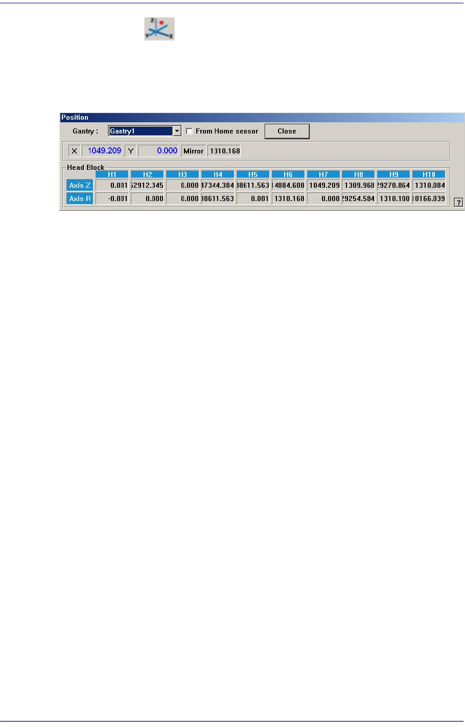
4.6. Current Position
Mainly used when the present coordinates of each driving axis need to be referenced for
teaching or calibration.
Figure4.6 “Position” dialog box
<Gantry> combo box
Select the gantry for which the coordinate is to be checked.
<From Home sensor> check box
This function is used to see how much the nozzle tip of the head has been lowered
from the position of the home sensor for the Z-axis.
Coordinates
X [When 1F-H1 is selected]
Indicates the present position in X direction of Head 1 at the origin of the
equipment.
Y [When 1F-H1 is selected]
Indicates the present position in Y direction of Head 1 at the origin of the
equipment.
Mirror
Indicates the presently rotated angle from the home position of mirror rotation axis
for fly camera.
Head Block group
Head 1/Axis Z
When the check box for <From home sensor> is not ticked, the height of the
nozzle tip of head 1 on the PCB is indicated.
Head 1/Axis R
Indicates the presently rotated angle from the home position of R axis for head 1.
Head 2/Axis Z
When the check box for <From home sensor> is not ticked, the height of the
nozzle tip of head 2 on the PCB is indicated.
Head 2/Axis R