Hanwha SM481 PLUS Series Administrator’s Guide Eng.pdf.pdf - 第190页
7-32 Fast Flexible Placer SM481(L) PLUS Administ r ator’s Guide Under-tolera n ce: Allows the t olerance less than the set value <Ungroup> button When the selec ted object is a lead group, cli cking thi s button …

7-31
Part Registration
<Position> combo box
When the lead is of Gull Wing, J Lead and Land type, selects the direction in
which the lead selected from the body center.
However, this menu is disabled when the selected object is a lead group.
Left / Right / Up / Down
<Pitch/ Pitch XY> edit box
Sets the distance between leads when the selected object is a lead group.
When the leads exist above/below the body center, input the lead interval in
the X direction.
When the leads exist at the left/right of the body center, input the lead pitch in
the Y direction.
<Foot> edit box
When the lead is of Gull Wing, J Lead and Land type, input the length of the
area where the lead comes into contact with the solder on the upper surface of
the PCB.
<X/ Y> edit box
Input the X and Y offsets between the vision window center and the center of
the selected object.
<Width> edit box
Input the width of an object to suit the image of an actual part. If the selected
object is round, input the diameter.
<Height> edit box
Input the height of an object to suit the image of an actual part. Only when the
selected object is rectangular is this enabled.
<Tolerance %> edit box
Even though there will be a difference between the recognized part shape and
the shape object of the registered part, input the allowable level as a
percentage.
For example, if the tolerance is set to 10%, the data of the registered shape
object is 10 and the shape data of the actually recognized part is 11, the vision
system considers that the shape of the recognized part is a normal shape.
In order to set detailed tolerance by major recognition parameter, click the
<Detail> button at the right.
<Detail> button
Sets the over-tolerance and under-tolerance for the length, width, foot and
pitch, respectively.
Over-tolerance: Allows the tolerance to exceed the set value
7-32
Fast Flexible Placer SM481(L) PLUS Administrator’s Guide
Under-tolerance: Allows the tolerance less than the set value
<Ungroup> button
When the selected object is a lead group, clicking this button will ungroup the
object.
<Fix proportion> switch button
Enabled when the selected object is a lead group. Selecting this button will
adjust the size of each lead by maintaining the ratio when adjusting the size of
the lead group.
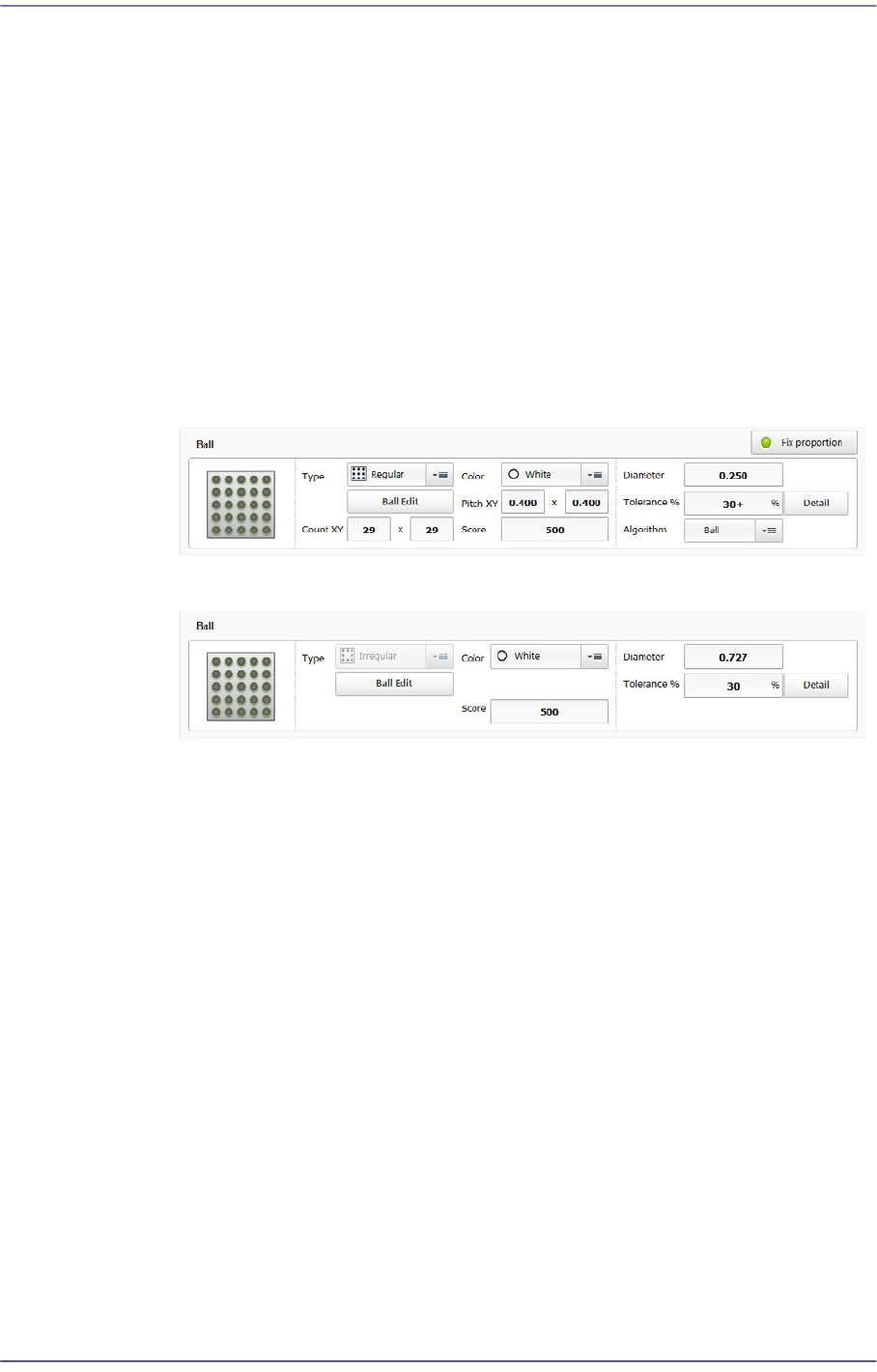
Ball/ Ball Group
Edits a ball shape to a defined object or deletes it.
The following shows the BGA.
The following shows the Flip Chip.
<Type> combo box
Selects the form of arrangement of the balls to be recognized.
Regular
Refers to the type where the ball arrangement is standardized.
Checker
Refers to the type with a standardized ball and ball gap.
Rev. Checker
Refers to the type where the ball and ball gap positions are changed in the
case of the Checker type.
Flip Chip
Refers to the type where irregular ball gaps exist.
<Edit Balls> button
Edits the ball arrangement. When the ball type is "Checker" or "Rev.
Checker", this button is disabled.
<Count XY> edit box
7-33
Part Registration
In the case of BGA, sets the number of balls in X and Y directions. In the case
of “Checker” or “Rev. Checker” type, the empty area is also reflected on the
number of balls. Therefore, in the case of “Checker” or “Rev. Checker” type,
the number of balls is always an odd number.
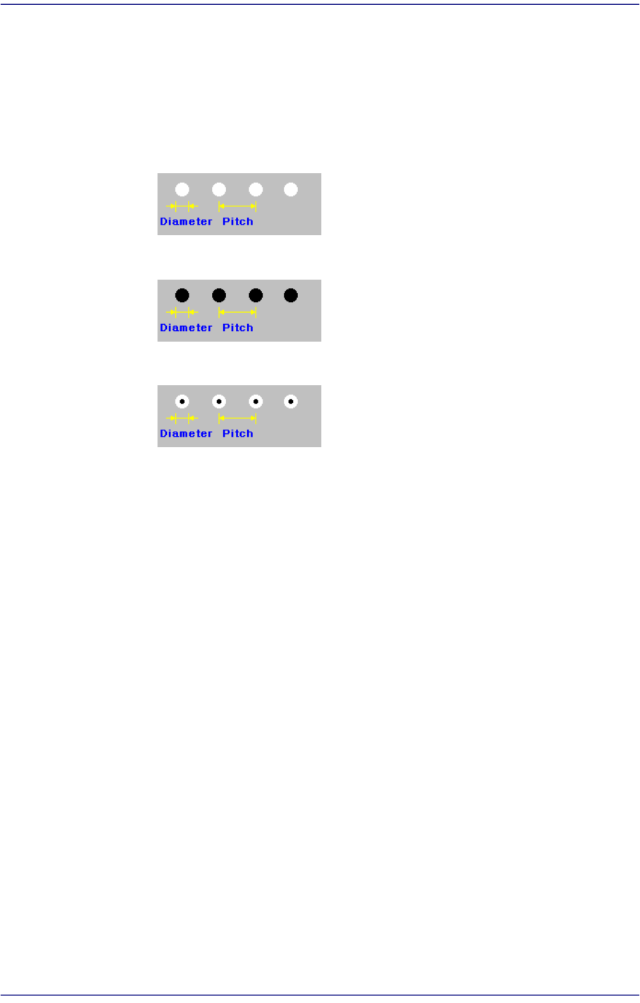
<BGA Flag> combo box
Selects the ball color.
White
Selected when the ball looks white.
Black
Selected when the ball looks black.
W & B (White and Black)
Selected when the center of the ball looks black and the outer side looks.
<Pitch XY> edit box
Enable only for BGA. Input the distance between the ball center and the center
of the adjacent ball in the X direction.
Input the distance between the ball center and the center of the adjacent ball in
the Y direction.
In the case of the “Checker” or “Rev. Checker” type, set the ball gap assuming
that there is a ball in the empty area.
<Score> edit box
The “Score” is the numerical value that indicates how accurately the ball
shape recognized by the vision system matches with the registered ball object
data.
For example, if this value is 1000, it means complete conformity. However, in
general, it is set to 600. If this value is too small, recognition accuracy
decreases, and if it is too great, the rejection result appears defective in many
cases.
<Diameter> edit box
Input the ball diameter.
<Tolerance%> edit box
Even though there will be a difference between the recognized part shape and