Hanwha SM481 PLUS Series Administrator’s Guide Eng.pdf.pdf - 第281页
9-7 Step Programming <Position T ype > combo box Select the number of fiducial marks. A vailable numbers of fiducial marks are as follows. None: No fiducial mark. 1 Part: 1 fiducial mark for placement point ad ju…
9-6
Fast Flexible Placer SM481(L) PLUS Administrator’s Guide
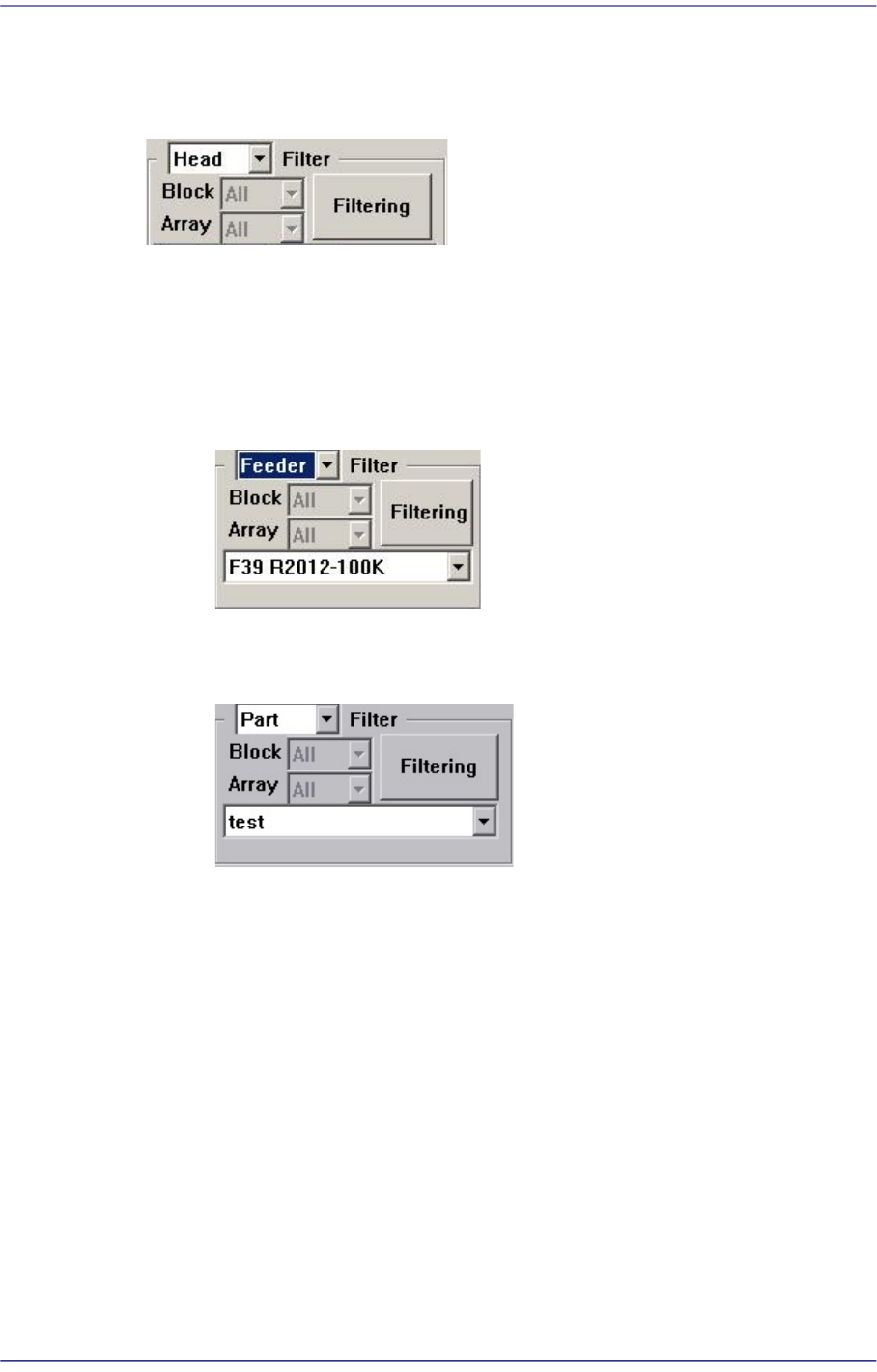
<Filter> Group
Designates the conditions for indicating the placement point shown in the Step dialog
box. Clicking the button will display the filtering function.
<Filter> combo box
Selects the conditions for indicating the placement point. Either ‘Feeder’ or ‘Part’
can be selected. Default is ‘Head’.
When Feeder is selected from the <Filter> combo box
Select the feeder for the part for which the placement point is to be indicated.
When Part is selected from the <Part> combo box
Select the part for which the placement point is to be indicated.
<Filtering> button
Indicates only the placement point that is filtered according to the condition
selected from the <Filter> combo box in the “Steps” dialog box.
<Insert 1Line> button
Adds a new placement point before the line (placement point) currently selected from
the <Grid>.
<2Pt. Teach> button
When a placement position is set, performs the function of teaching 2 corner points,
calculating the center point and using it as the placement point. Please refer to “8.1.1
Feeder Base”<2Pt. Teach…> button for more information.
<Fiducial…> button
If the placement point has a fiducial mark, sets the fiducial mark data. Closes the
dialog box without saving the changed contents.
9-7
Step Programming
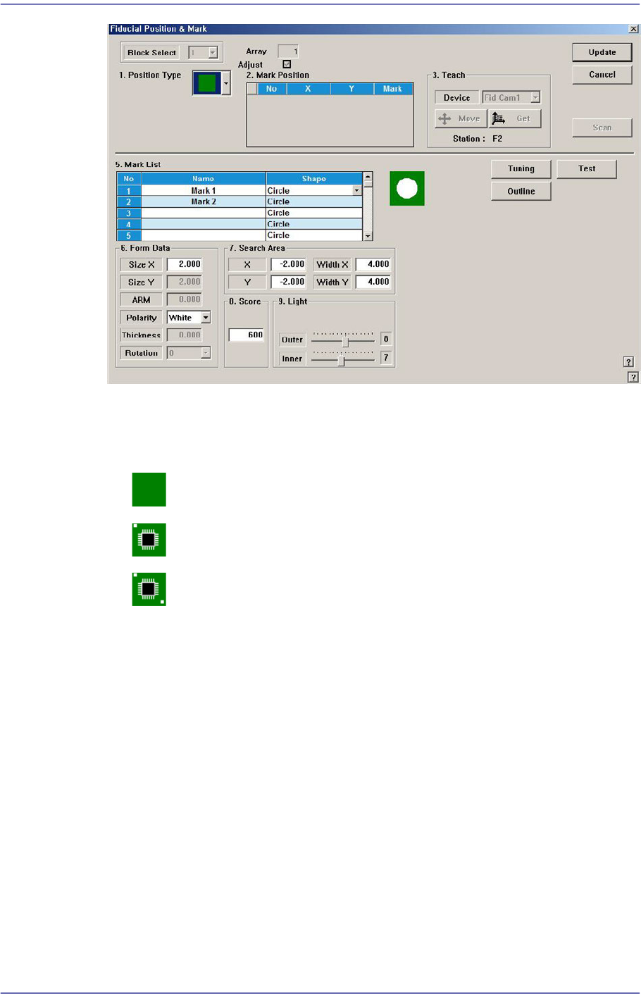
<Position Type> combo box
Select the number of fiducial marks. Available numbers of fiducial marks are as
follows.
None: No fiducial mark.
1 Part: 1 fiducial mark for placement point adjustment.
2 Part: 2 fiducial marks for placement point adjustment.
Please refer to “6.3. Fiducial Mark Setup” for more information.
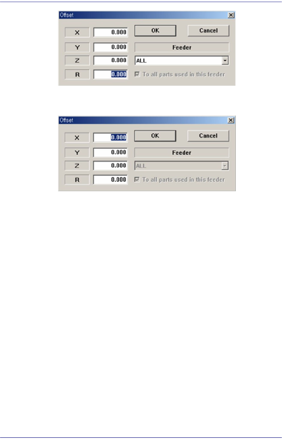
<Offset…> button
Adds the offset value to the position of placement point. Before executing this
function, X column or Y column or Z column or R column or the line to add the offset
value must be selected in the grid. When this button is clicked on, the following dialog
box is displayed.
<When one of X, Y, Z, and R is selected>
Apply the offset value to the selected part.
9-8
Fast Flexible Placer SM481(L) PLUS Administrator’s Guide
<When the row is selected>
Apply the offset value to all parts.
<X> edit box
Set the X offset value.
<Y> edit box
Set the Y offset value.
<Z> edit box
Set the Z offset value.
<R> edit box
Set the R offset value.
<OK> button
Closes the dialog box and adds the set offset value to the selected line in the grid.
<Cancel> button
Ignores the set offset value and closes the dialog box
<Adjust…> button
It is a function used to change the PCB step coordinate or to check and adjust the gap
between the previous fiducial mark coordinate and the current fiducial mark
coordinate to use the previous step coordinate when the backup table is down
accidentally.
<Clear Cycle> button
Initialize the placement cycle.