Hanwha SM481 PLUS Series Administrator’s Guide Eng.pdf.pdf - 第371页
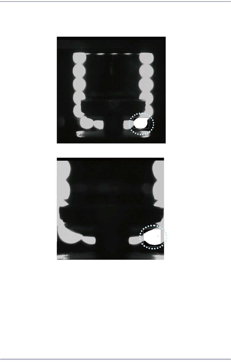
14-19 Machine Calibration bottom righ t . Set the Pixel Count Percentage t o a value greater than 90% for testing. <In the case of f l y-camera with FOV 2 5mm> <In the case of f l y-camera with FOV 1 6mm>
14-18
Fast Flexible Placer SM481(L) PLUS Administrator’s Guide
Nozzle Offset Teaching
1) If the Offset X and Y cells are clicked, the <Test> button is activated. At this
time click the <Test> button
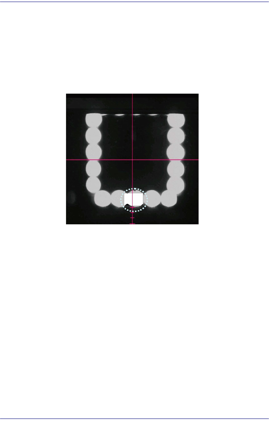
2) The area to be tested is displayed in the box shape of the ‘SMVision’ window.
Set the value of OffsetX and OffsetY so that the test box comes to the center
of the bottom of the LED. The coordinate system used to set the X and Y
values is the Right-Down coordinate system.
After clicking the <Test> button, SMVision window
Nozzle Count Teaching
1) If the Offset X and Y cells are clicked, the <Test> button is activated. At this
time click the <Test> button.
2) The area to be tested is displayed in the box shape of the ‘SMVision’ window.
Set the Count X (Width) and Count Y (Height) to change the box size so that
the Pixel CountPercent becomes greater than 90% when clicking the <Test>
button. The box size is changed based on the previously set Offset X and Y
values.
Light Offset Teaching
Despite the fact that the nozzle is thought to exist when the Pixel CountPercent is
less than ‘30’, this light offset teaching is performed to prepare for the case that
the light is not turned on due to the fault of the LED. Set this area after inserting
the largest nozzle.
The only difference between Nozzle Offset Teaching and Nozzle Count Teaching
is the position of the test box.
1) If the Offset X and Y cells are clicked, the <Test> button is activated. At this
time click the <Test> button.
2) When clicking the <Test> button, the test box is the bright area (LED) on the
14-19
Machine Calibration
bottom right. Set the Pixel Count Percentage to a value greater than 90% for
testing.
<In the case of fly-camera with FOV 25mm>
<In the case of fly-camera with FOV 16mm>
14-20
Fast Flexible Placer SM481(L) PLUS Administrator’s Guide
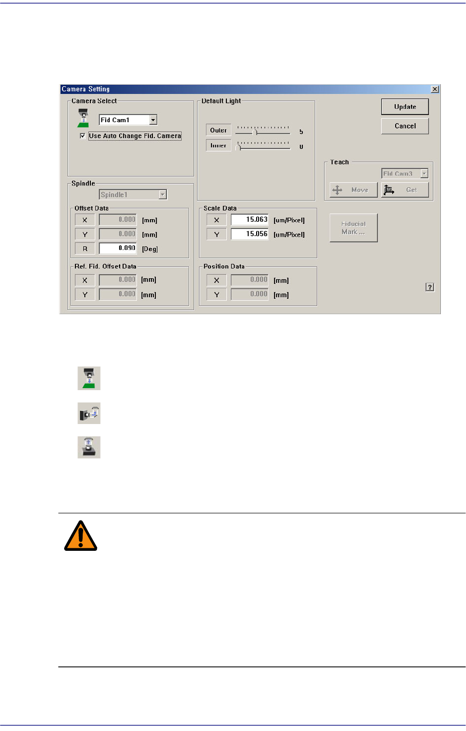
14.2. Camera [F5]
Sets various data on the camera.
Figure14.7 “Camera Setting” dialog box
<Camera Select> combo box
Select the camera type to set. Available camera types are as follows.
Move Camera: Camera used for position teaching or fiducial mark check.
Fly Camera: Camera used for component check, it is attached to each head.
Fix Camera: Camera used for component check, it is fixed on the machine
base.
Above screen is the case where the camera type is set to “Fiducial Camera”.
Warning Operation error caused by unauthorized or untrained
personnel or insufficient checking before calibration could
severely damage the equipment or the set up data, or it
could cause personal injury of the operator or the worker
near the equipment. Before carrying out calibration, check
the item to be calibrated and check if there is any worker
near the equipment. And calibration must be carried out by
an authorized and trained user only.