Hanwha SM481 PLUS Series Administrator’s Guide Eng.pdf.pdf - 第438页
15-2 Fast Flexible Placer SM481(L) PLUS Administ r ator’s Guide 15.1. Co nveyor [F3 ] Sets the conveyor related items. Figure15.3 “C onveyor Configuration ” dialog box 1: Curr e n t Define ‘Current Defin e’ group Displ…
15-1
System Setup
Chapter15. System Setup
Describe system setups except for the calibration items mentioned in the preceding
chapter.
The items on this menu are setup at the time of shipment. Therefore, do not perform
“Calibration System Setup” except when setup is required for the maintenance of the
machine.
Warning hanging the set up status by an unauthorized user could
damage the equipment or result in personal injury.
Unauthorized user must not change the set up status of the
equipment.
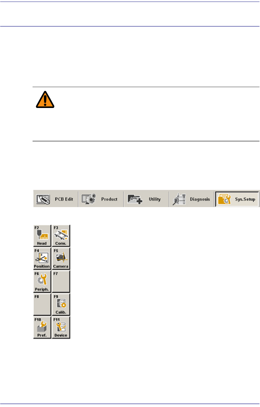
When a submenu of the <Sys. Setup> menu is selected, corresponding dialog box is
displayed on the screen. While the corresponding dialog box is displayed, selecting the
menu once more activates the dialog box.
Figure15.1 When the Sys. Setup menu is selected
Figure15.2 Submenus of the Sys. Setup menu
15-2
Fast Flexible Placer SM481(L) PLUS Administrator’s Guide
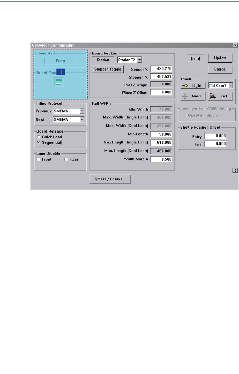
15.1. Conveyor [F3]
Sets the conveyor related items.
Figure15.3 “Conveyor Configuration” dialog box
1: Current Define
‘Current Define’ group
Displays the setup status of the current conveyor.
<Fixed Rail> group
Displays type of conveyor fixing (front/rear).
<Board Flow> group
Displays the direction of the conveyor board (right->left/ left->right).
<Inline protocol> group
Select the in-line protocol for the previous and next equipment from the Combo Box.
Stand alone: Operates the equipment separately without performing line operation.
Busy input only: Uses the protocol specified by the company which developed the
equipment as a communication protocol between the previous and next equipment
when performing line operation.
SMEMA: Uses the SMEMA protocol as a communication protocol between the
previous and next equipment when performing line operation.
15-3
System Setup
<Board Release> option button group
<Quick Load> option button
Click this button to minimize the time between PCB departures and arrivals. This
feature instructs the transport rail to acquire a new PCB immediately after the
machine release the current PCB.
<Sequential> option button
Click this button to instruct the transport rail that a PCB departing the downstream
station must exit completely before allowing the next PCB to enter.
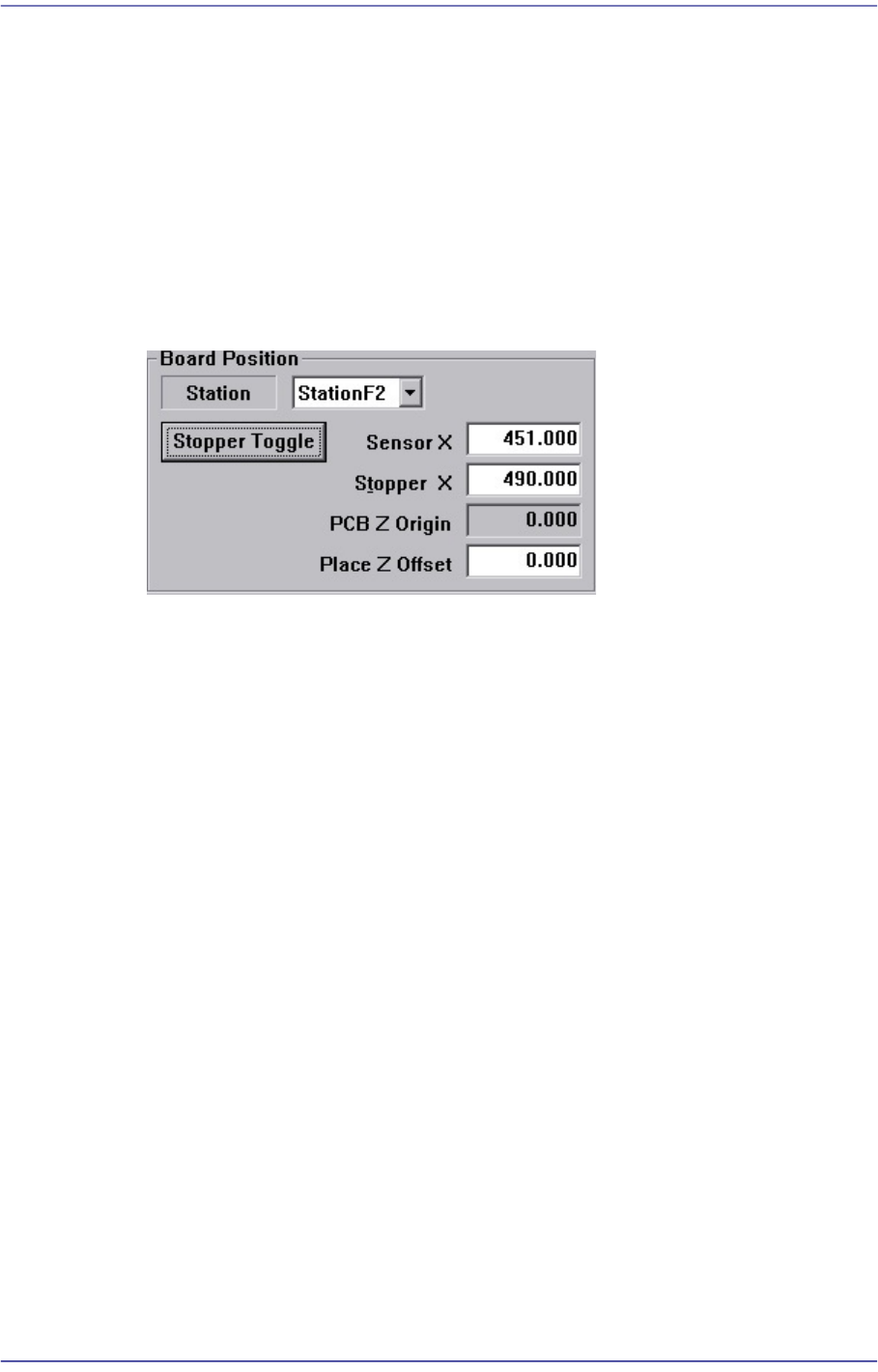
<Board Position> group
<Station> combo box
Select Working Station.
<Sensor X> edit box
Set the coordinate of the PCB detection sensor at the selected station.
<Stopper X> edit box
Set the coordinate of the stopper at the selected station.
<PCB Z Origin> edit box
Displays the calibration value to be used to calibrate the difference between the
top surface of the ANC and the top surface of the PCB.
<Place Z Offset> edit box
Used to place the part by pressing the part in the Z axis direction as much as the
offset that was set here.
<Stopper Toggle> button
It is used to move the stopper up or down when teaching the stopper position.
<Rail Width> group
Sets the data related to the conveyor width adjustment.
Min. Width
Shows the minimum width of Transport rail.