Hanwha SM481 PLUS Series Administrator’s Guide Eng.pdf.pdf - 第404页
14-52 Fast Flexible Placer SM481(L) PLUS Administ r ator’s Guide 14.3.7.4. Camera Offset Calibration Measure the off s et between the cente r of the fiducial camera and the first head (Head 1, Head7) of each gantry . Thi…
14-51
Machine Calibration
14.3.7.3. Fiducial Cameras Offset Calibration
Measure the offset between the center of the 1st fiducial camera and 2nd fiducial camera.
In order to calibrate the fiducial camera offset, the ‘Fix-Camera Calibration’ and the
‘Fiducial Camera Scale Calibration’ must be preceded.
In order to perform the calibration, use the calibration Tool.
The following is the procedure to calibrate the Fid Cam Offset of the head;
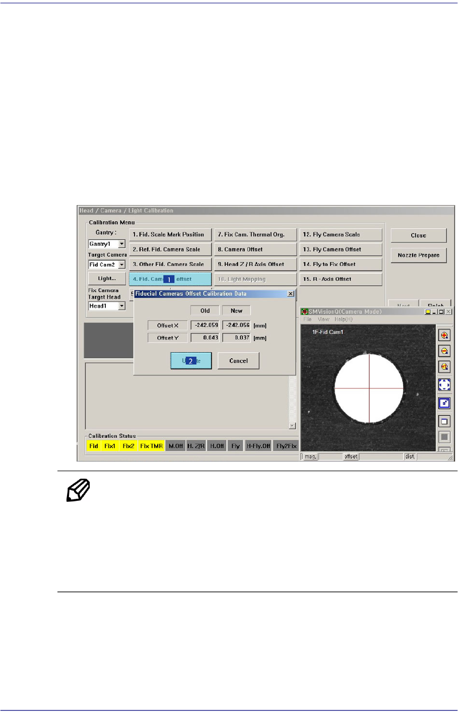
1. Click the <4. Fid Cameras Offset> button.
2. The calibration is performed automatically. If it is completed, the calibration result is
displayed as shown in the following figure. Click the <Update> button to apply the
new calibration value.
Memo The reference values for the calibration of the Fiducial Camera
Offset(FOV 7.5)is as follows.
Gantry1
Offset X : -243.0mm ~ -241.0mm
Offset Y : -1.0mm ~ 1.0mm
14-52
Fast Flexible Placer SM481(L) PLUS Administrator’s Guide
14.3.7.4. Camera Offset Calibration
Measure the offset between the center of the fiducial camera and the first head (Head 1,
Head7) of each gantry.
This offset measurement must be completed to be able to use the Auto Nozzle Change
function for calibrations that follow. This process is performed only in the Manual Mode.
In order to perform calibration of Fly-Camera Scale Calibration, first check if the
calibration tool is placed on the calibration tool position of the front ANC.
The following is the procedure to calibrate the Fid Cam Offset of the head;
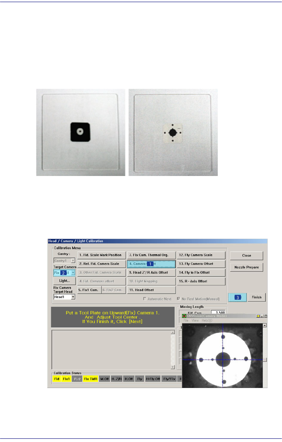
1. If the <8. Camera Offset> button is clicked, the message “Put a Tool Plate on
Upward(Fix) Camera 1. And Adjust Tool Center. If you Finish it, Click [Next].”
appears in the message box. Click the <Next> button to move down the Z axis of the
head in order to remove all nozzles inserted in the nozzle-holder manually.
14-53
Machine Calibration
Memo Only when the Calibration Glass is properly aligned with the center of
the Fix Camera can calibration be performed. Place the Calibration
Glass correctly referring to the following figure.
2. The message, “Move To Center Position of [Fix 1] Camera. To Move, Click [Next]” is
displayed in the message window. Click the <Next> button to move the head assembly
to the center of the Fix 1 Camera.
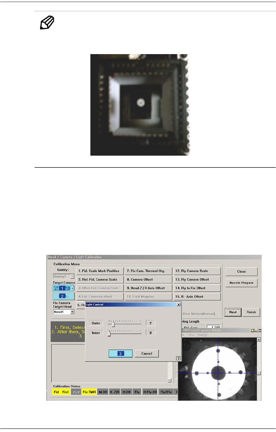
3. The message “1. First, Select Move Camera and Adjust Light Level. 2. After that,
Select Fix-camera and Adjust Light Level. 3. To Calibrate, Click [Next]” appears.
Then click the <Light…> button first and adjust the brightness of the light in the Light
Control’dialog box so that the white circle at the center of the Calibration Glass that is
seen in the ‘SMVision’ window can be seen clearly.
4. Then select the ‘Fix1 Cam’ in the <Target Camera> combo box and click the