Hanwha SM481 PLUS Series Administrator’s Guide Eng.pdf.pdf - 第220页
7-62 Fast Flexible Placer SM481(L) PLUS Administ r ator’s Guide 7.2.2.7. COMMON DATA Sets the handling parameters related to part pickup and placement. 1: Common Parameter <Package> tab Sets the parame t ers rela…

7-61
Part Registration
Inputs the pin length. Input the distance between the part bottom surface
contacting the PCB and the end of the pin.
<Recognition Height Z (mm)> edit box
Input the height for part recognition. When recognizing the upper side based on
the bottom surface, set the height to a minus (-) value, and when recognizing the
lower side, input the height to a plus (+)value.
<Get Align Z> button
When this button is clicked, the machine automatically measures the height at
which the part is recognized, and the measured value is entered in the
<Recognition Height Z> edit box.
<Side Recog. Option> group
<Side View Use> check button
Selected when checking for defective part pickup using a Side View Camera
(SVS).
For 0402 ~ 1608 chip parts, apply this function.
<SVS Validation Area -> edit box
Even though the value measured by the camera is slightly smaller than the height
(thickness) of the registered part, input the allowable range by which the currently
picked part is considered effective. The unit is in mm. Use the default set value.
If 0.05 is inputted while the height of the registered part is 0.2, when the part
height measured by the SVS camera is greater than 0.15 and less than 0.20, the
vision system considers that the currently picked part is effective.
<SVS Validation Area +> edit box
Even though the value measured by the camera is slightly greater than the height
(thickness) of the registered part, input the allowable range by which the currently
picked part is considered effective. The unit is in mm. Use the default set value.
<Side View After Pickup> Check box
Enabled when the <Side View Use> check button is selected. Selected in cases to
check for part pickup using the SVS camera after picking up a microchip.
<Side View After Place> Check box
Enabled when the <Side View Use> check button is selected. Selected in cases to
check for part placement using the SVS camera after placing a microchip.
<Side View After Dump> Check box
Enabled when the <Side View Use> check button is selected. Selected in cases to
check for part dumping using the SVS camera after dumping a microchip.4
<Recommend SVS> button
Applies the default value to all part parameters related to the SVS.
7-62
Fast Flexible Placer SM481(L) PLUS Administrator’s Guide
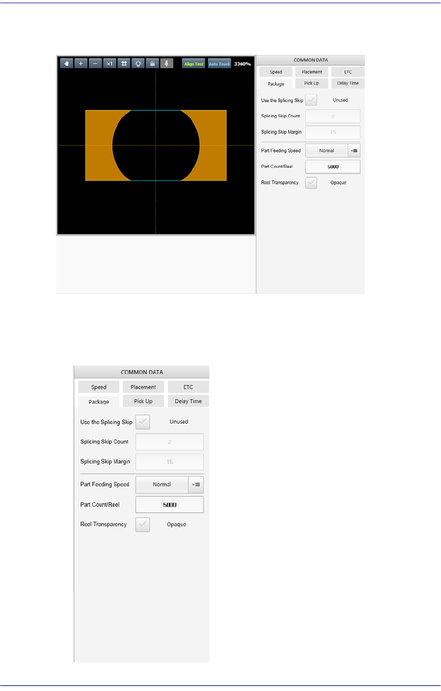
7.2.2.7. COMMON DATA
Sets the handling parameters related to part pickup and placement.
1: Common Parameter
<Package> tab
Sets the parameters related to part supply and pickup.
7-63
Part Registration
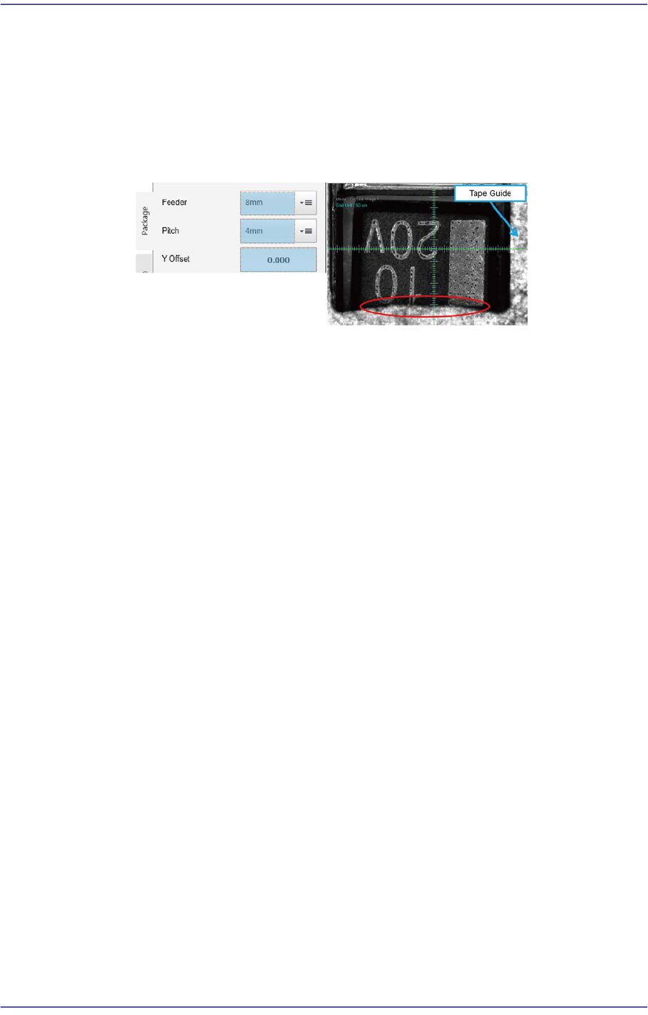
<Feeding Y Offset> edit box
Used when supplying parts by setting the pitch of the 8mm tape feeder to 4mm.
If the size Y of the part is greater than 2.2mm, the part pickup may interfere with
the tape guide.
In this case, it is possible to set the part pickup position by inputting the Y offset
value in the <Y Offset> edit box. (Input range: 0 ~ 0.5mm)
<Use the Splicing Skip> check button
The splicing skip function is to supply parts by skipping some parts in the section
where existing tape is spliced with a new tape in the tape feeder since parts are not
supplied at this connected section.
When using this function, select this check box.
<Splicing Skip Count> edit box
If the splicing check sensor detects a spliced section, parts are supplied by
skipping as many parts as is set here.
<Splicing Skip Margin> edit box
Inputs the number of parts to be skipped in addition to the part count set in the
<Splicing Skip Count> edit box.
<Feeding Speed> selection box
Selects the feeding speed of the tape feeder selected from the <Feeder> selection
box.
In the case of a micro part, it may jump up and cause a pickup error during part
feeding. This problem may be solved by reducing the part feeding speed.
Normal: Supplies parts at normal speed.
Slow1: Supplies parts at a slightly slower speed.
Slow2: Supplies parts at slow speed.
<Part Count/Reel> edit box
Input the default number of parts for the part reel that supplies the corresponding
part. When using the Basic IT function, it is used as default count for the
corresponding part.
<Reel Transparency> check box
When splicing the tape using transparent tape, this function is selected in the case