Hanwha SM481 PLUS Series Administrator’s Guide Eng.pdf.pdf - 第363页
14-11 Machine Calibration Nozzle Compares the binary v a lue of the pixel in a specific ar ea when the nozzle is inserted and when it is not i n the nozzle-holder in order to check the existence of the nozzle. At t his…
14-10
Fast Flexible Placer SM481(L) PLUS Administrator’s Guide
<Add Offset> group
It is possible to apply X, Y and R placement offsets collectively to all heads.
This function is used at the factory. Users must not apply the offsets at their own
discretion.
<Update> button
Transmits the change data to the equipment and closes the dialog box.
<Cancel> button
Ignores the change data and closes the dialog box.
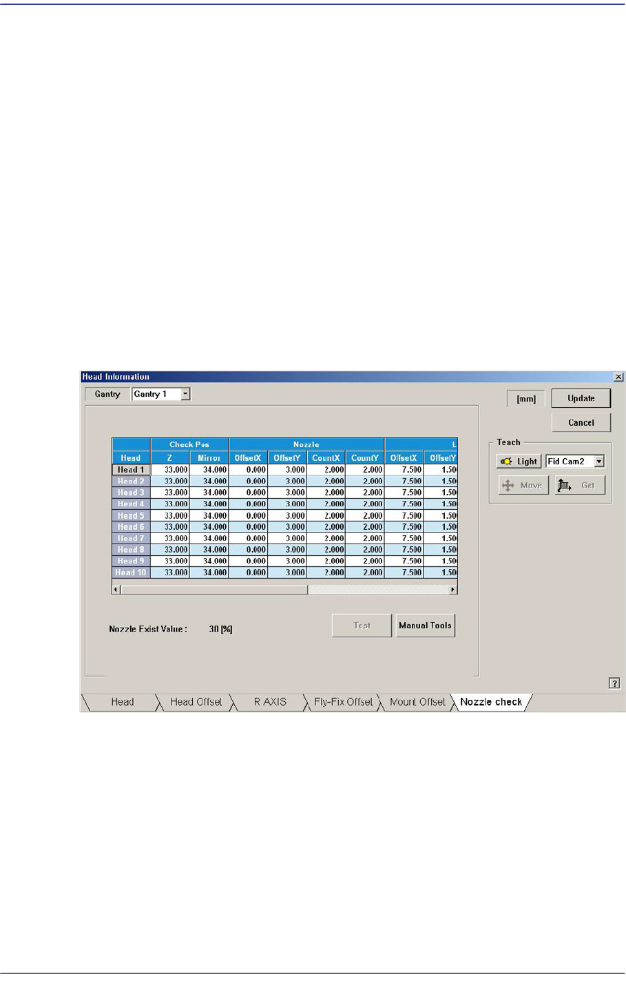
14.1.6. “Nozzle Check” tap dialog box
This nozzle-check function is used to check whether the nozzle is inserted in the nozzle-
holder of the head or not by using the fly-camera.
Figure14.6 “Nozzle Check” tab dialog box
Check Pos
Z
Refers to the height of the Z-axis of the corresponding head when checking the
existence of the nozzle. This is indicated by the distance from the top surface of
the PCB to the end of the head-spindle. Therefore, the nozzle inserted in the
nozzle-holder must be removed before performing setup of the Z-axis.
Mirror
Refers to the position of the mirror axis when checking whether the nozzle is
mounted or not. This is indicated as degree.

14-11
Machine Calibration
Nozzle
Compares the binary value of the pixel in a specific area when the nozzle is inserted
and when it is not in the nozzle-holder in order to check the existence of the nozzle.
At this time, this specific area is called a test area, and is displayed in box shape in the
vision screen.
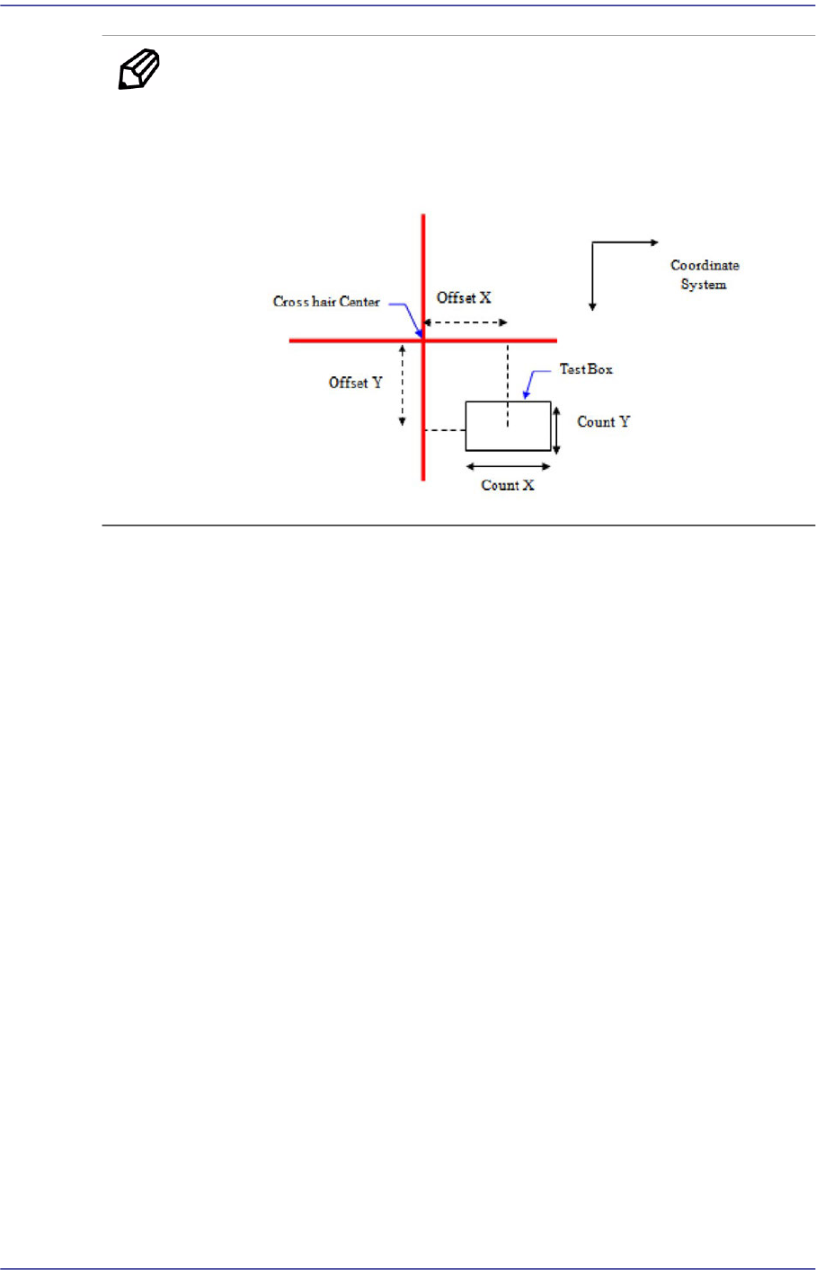
Offset X / Offset Y
When the distance from the cross hair center to this rectangular box (i.e. center of
the test box) in the vision screen is indicated in the Right-Down coordinate
system, the distance in the X-direction is called ‘Offset X’ and the distance in the
Y-direction is called ‘Offset Y’.
Count X / Count Y
The size of the test box in the X-direction is called ‘Count X’ and the size in the Y-
direction is called ‘Count Y’.
Light
When examining the existence of the nozzle through the fly-camera, the lighting is the
decisive factor in determining the binary value of the pixel in the test box area.
Therefore, the area for examining whether the lighting system has a problem or not
must be set up in order to check any problem with the lighting conditions when
checking the existence of the nozzle through the fly-camera. At this time, insert the
biggest nozzle in the nozzle-holder to examine if the nozzle interferes with the area to
be checked.
This area is displayed in rectangular box shape in the vision screen.
Offset X / Offset Y
When the distance from the cross hair center to this rectangular box (i.e. center of
the test box) in the vision screen is indicated in the Right-Down coordinate
system, the distance in the X-direction is called ‘Offset X’ and the distance in the
Y-direction is called ‘Offset Y’.
Count X / Count Y
The size of the test box in the X-direction is called ‘Count X’ and the size in the
Y-direction is called ‘Count Y’.
14-12
Fast Flexible Placer SM481(L) PLUS Administrator’s Guide
Memo When activating the <Test> button, the Offset or Count cell must be
clicked.
The coordinate system in the following figure is obtained from the
cross hair center of the vision screen.
<Test> button
Sets the nozzle recognition condition and lighting condition by testing the binary value
of the pixel for the certain area (test box) that is set using the fly camera.
When the binary value of the pixel for the area that is used to check whether the nozzle
is mounted or not is below 30%, the nozzle is considered to be mounted. If the value is
above 30%, the nozzle is not considered to be mounted. If a nozzle actually exists, the
value must be close to ‘0’, if a nozzle does not exist, the values must be close to ‘100’.
<When the nozzle is mounted on the head>