Hanwha SM481 PLUS Series Administrator’s Guide Eng.pdf.pdf - 第395页
14-43 Machine Calibration <Gantry> combo box Select the Gantry for performing Calibra t ion <T arget C amera> combo box Select the camera to set light value. <Light…> button Set the light value fo…
14-42
Fast Flexible Placer SM481(L) PLUS Administrator’s Guide
14.3.7. Head & Camera Calibration
Perform the camera calibration function. The calibration sequence and tools necessary for
calibration are as follows.
Fix Camera Scale Calibration (CNT20 Nozzle)
Fix Camera Thermal Origin
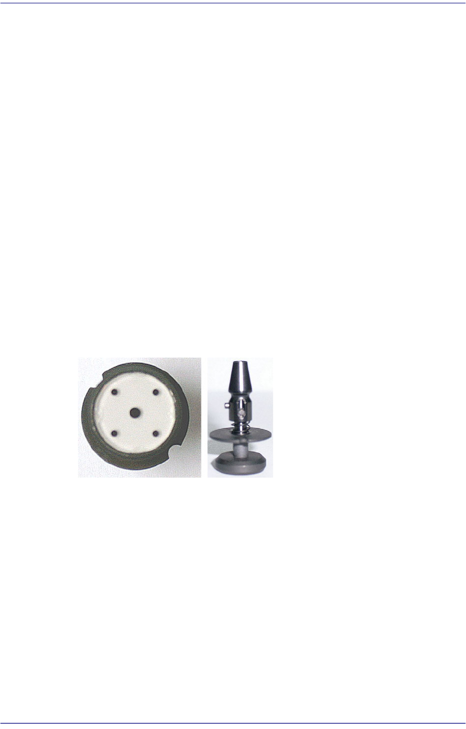
Fiducial Cameras Offset Calibration (Calibration Tool)
Cameras Offset Calibration (Calibration Glass)
Head Z & R Offset Calibration (CN040 Nozzle)
Light Mapping (Light Fly Nozzle)
Head Offset Calibration
Fly Camera Scale & Rotation Calibration
Fly Camera Offset Calibration
Fly To Fix Offset Calibration
R-Axis Offset Calibration
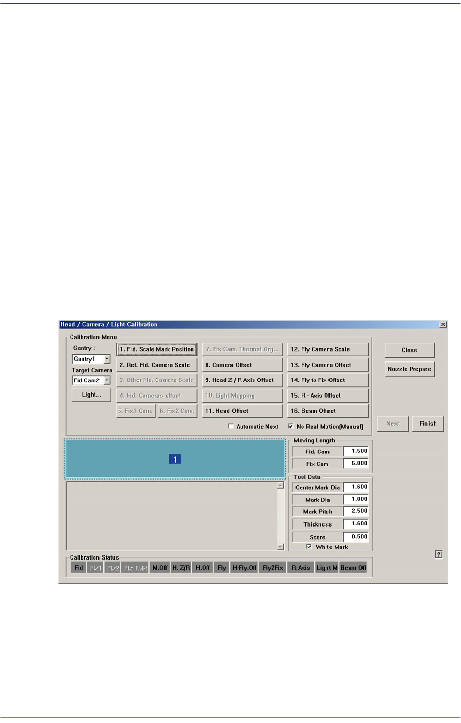
Figure14.13 “Head/ Camera/ Light Calibration” dialog box
1: Head/ Camera/ Light Calibration” dialog box
<Calibration Menu> group
Select an item to be calibrated. If you click the button of a specific item, the
description on the works to be performed are displayed in the message box in order.
Follow the instructions to complete the calibration.
14-43
Machine Calibration
<Gantry> combo box
Select the Gantry for performing Calibration
<Target Camera> combo box
Select the camera to set light value.
<Light…> button
Set the light value for the selected camera.
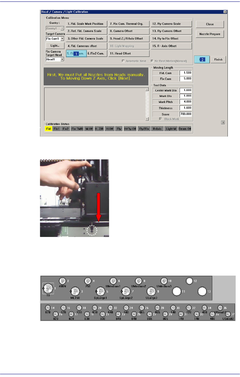
14.3.7.1. Fix Camera Scale Calibration
The fix camera calibration must be performed before performing fiducial camera offset
calibration.
First, teach the fiducial mark on the upper surface of the fix camera and perform
calibration of the fix camera scale using the CNT20 nozzle.
<5. Fix 1 Camera> button
This calibration is performed to calibrate the Scale (um/pixel), Rotation (deg) and
Position (mm) of the fix-camera.
In order to perform this calibration first, the R-Offset Calibration must be performed in
advance and the calibration-nozzle must be used. Use Hole #1 as the ANC hole
exclusively used for the calibration-nozzle.
The following is the procedure to calibrate the Fix Camera Scale;
1. If the <5. Fix1 Camera> button is clicked, the message “First, We must Put all Nozzles
From Heads on Manually. To Move down Z Axis, Click [Next]” appears in the
message box. Click the <Next> button to move down the Z axis of the head in order to
manually move all nozzles inserted in the nozzle holder of the head.
14-44
Fast Flexible Placer SM481(L) PLUS Administrator’s Guide
2. Then, after the head assembly moves to the designated position, move all Z axes
down. At this time, remove all inserted nozzles manually
3. “Then the message “Next Attach the Calibration Tool to Head 1. Click [Next] for
Moving Down Head. After Moving, Attach the Tool to head Manually” appears. Click
the <Next> button after inserting the CNT20 nozzle at nozzle holder of Head #1
manually.
4. The message “Move To Center Position of Calibration Tool. To Move, Click
[Next].”appears. appears in the message window. Click the <Next> button to move the
head assembly to the calibration tool position on the ANC.