Hanwha SM481 PLUS Series Administrator’s Guide Eng.pdf.pdf - 第307页
11-1 Cycle Check Chapter11. Cycle Check 11.1. Cyc le Check Check for any errors in currently loaded PCB fi l es. If an error occurs, check th e details of the error in the m essage window a nd modify the PCB fil e to sol…

10-16
Fast Flexible Placer SM481(L) PLUS Administrator’s Guide
<Placement> group
Indicates the number of parts, number of total placement points, number of times of
nozzle replacement and total hours of working. The total working time is the estimated
time by simulation. It may be more or less different from actual pick and placement
time due to defective component recognition and other reasons.
<Feeder /Nozzle /ANC Arrangement> group
Indicates the arrangement status of tape feeder, ANC, and nozzles.
Pre: Number of tape feeders directly arranged by the user.
New: Number of tape feeders directly arranged by the optimizer.
Total: Total number of arranged tape feeders.
<Pickup> group
The distribution of simultaneous component pickups is displayed in this group. The
number of pickup points and its percentage for each pickup type is displayed in this
group.
I: Component pickups by one head only (individual pickup)
xS: x number of heads pick up components simultaneously
<Cycle> group
Indicates the final arrangement status of parts, feeders and nozzles of the step
program. Three radio buttons on the bottom let the user to select one and see the
allocation status. The number in the right most column displays the number of cycle
repetitions.
Component
In the component arrangement status, the component to be operated by each head
is displayed as cx, x is the number given to a component. (Component name is not
displayed here)
Feeder
In the feeder arrangement status, the feeder lane from which the head picks up is
displayed. The front feeder base is indicated by Fx, and the rear feeder base by Rx.
Here x is the feeder lane number. And, the stick feeder is indicated by Sx, and the
tray feeder by Tx.
Nozzle
The nozzle arrangement status shows which nozzle is used for which head. The
name of the nozzle to be attached to each head is displayed.
11-1
Cycle Check
Chapter11. Cycle Check
11.1. Cycle Check
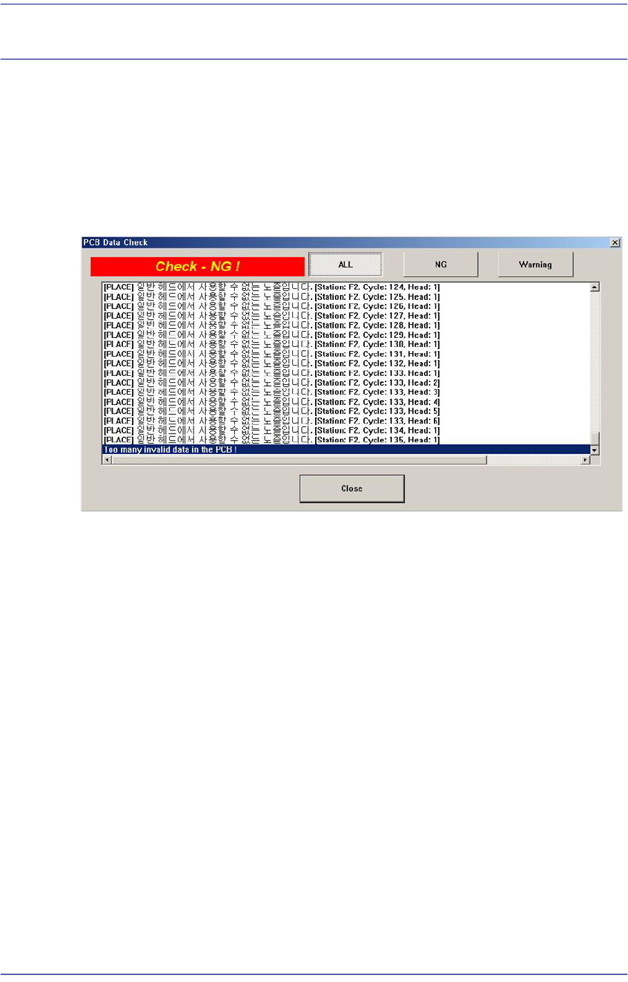
Check for any errors in currently loaded PCB files. If an error occurs, check the details of
the error in the message window and modify the PCB file to solve the corresponding error.
If the cycle check exhibits no problem, an error does not occur when executing a ‘PCB D/
L’ command in the Production menu. Consequently, only when the cycle check finds no
error can PCB production commence properly.
<ALL> button
Displays all NG and warning messages.
<NG> button
Displays only the NG messages.
<Waring> button
Displays only the warning messages.