Hanwha SM481 PLUS Series Administrator’s Guide Eng.pdf.pdf - 第313页
12-5 LED placement : T riangle mark in the 180° direction. : T riangle mark in the 270° direction. : The re is a re cess or protrus ion at t h e bottom su rface of the part in the left directi on. (concavo-convex) …
12-4
Fast Flexible Placer SM481(L) Administrator’s Guide
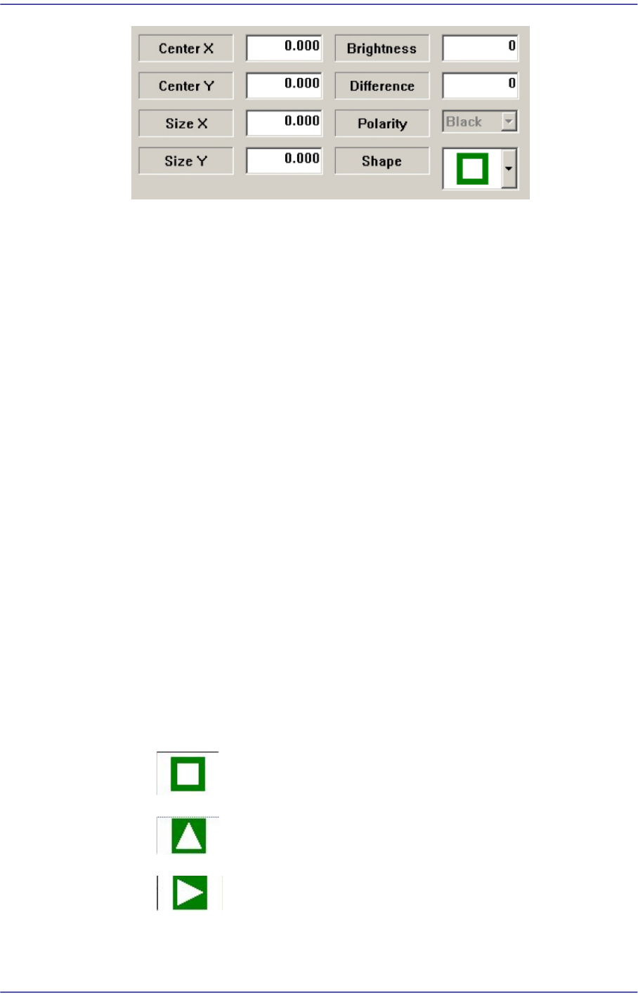
Center X
Refers to the coordinate in the X direction of the Black area based on the part
center. (Refers to the figure in the dialog box)
Center Y
Refers to the coordinate in the Y direction of the Black area based on the part
center. (Refers to the figure in the dialog box)
Size X
Size of the tetragonal area in the X direction (mm)
Size Y
Size of the tetragonal area in the Y direction (mm)
Brightness
Refers to the reference value of the White area. The White area with a value
greater than the reference value can be considered normal.
Difference
Input the minimum difference in the brightness between <Area 1> and <Area
2>. Generally, input 40.
Shape
Select a shape according to the mark or concavo-convex on the bottom surface of
the LED. If the concavo-convex shape is selected, the brightness of the selected
area as well as the direction of a protrusion are checked. This, therefore, prevents
the part from being placed upside down.
: There is no shape.
: Triangle mark in the 0° direction.
: Triangle mark in the 90° direction.
12-5
LED placement
: Triangle mark in the 180° direction.
: Triangle mark in the 270° direction.
: There is a recess or protrusion at the bottom surface of the part in
the left direction. (concavo-convex)
: There is a recess or protrusion at the bottom surface of the part in
the right direction. (concavo-convex)
: Refers to cases where work is performed on Lumens LED and a
circular shape is engraved on the bottom surface of a part.
Select the option function used when recognizing the LED using the vision system
in the <Data Setting> group.
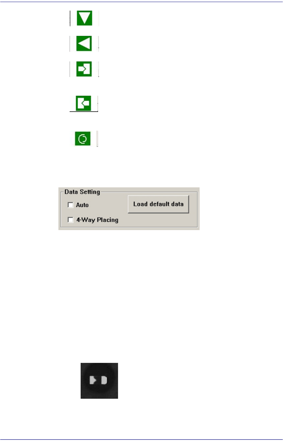
<Auto> check box
When there is a black area on the LED bottom surface (surface to be
recognized by the vision system) without specific marks such as a tetragon or
triangle on it, if this check box is selected, this image is considered to be one
of the images shown below.
<4-Way Placing> check box
When recognizing an LED part, if it was picked up being turned 180°, this
function allows the part to be placed by turning it 180° without dumping it.
Mainly, this function is enabled when using a bowl feeder.
In order to use this function, the characteristics, position and size of the LED
mark must be inputted correctly. When there is a symmetrical mark on the
bottom surface of the part, exercise care not to use this function.
: OK –Considered to be picked up normally.
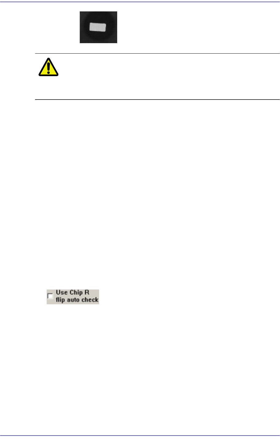
12-6
Fast Flexible Placer SM481(L) Administrator’s Guide
: NG –Considered to be picked up upside down.
Caution The corresponding function can be used only for a bowl
feeder. When supplying parts using a bowl feeder, this
function must be selected.
<Load default data> button
Shows examples for inputting an LED mark, and indicates the default value
saved in the system regardless of the part actually picked up.
This function is a guide for inputting certain types of value. Since this data has
nothing to do with the part to be actually placed, use the data for reference
only.
In addition, when it is desired to return all values inputted back to the default
value, this function can be used.
It is possible to judge whether inputted values for ‘Area 1’ and ‘Area 2’ are
appropriate by clicking the <Outline> button.
Whether to recognize the polarity must be checked by clicking the <Test> button.
If the recognition result is ‘OK’, when the <Test> button is clicked again, with the
part being turned 180° manually using the jog box, check whether the recognition
result is ‘NG’.
If the setup has been performed properly, click the <Close> button to save the set
value.
<Use Chip R flip auto check>
This is used only in the Part Edit Screen for Chip R part. It is selected to use the
function that checks the turnover of the Chip R part.
(Chip-R3216, Chip-R2012, Chip-R1608, Chip-R1005, Chip-R0603, Chip-R0402 etc.)
<Move> button
Tests component recognition by using the set align data. Please refer to“7.1.1
Common Align Data” for more information.
<Test> button
Tests component recognition by using the set align data. Please refer to“7.1.1
Common Align Data” for more information.
<Image Capture> button