Hanwha SM481 PLUS Series Administrator’s Guide Eng.pdf.pdf - 第236页
7-78 Fast Flexible Placer SM481(L) PLUS Administ r ator’s Guide value is 0.2000 and its range is 0.10 0 0~5.000. <Flux Dipping Inspect> check box Recognizes the shape of flux app l ied on the balls of BGA parts. …
7-77
Part Registration
<Flux Type> selection box
Selects the method for flux part recognition. This function can be used for the
machine equipped with a flux device.
No Flux
Selected when the part is not a flux part. If this option is selected, the POP
function cannot be used.
Post Flux
Selected in cases to recognizes a part after dipping it into flux.
Pre Flux
Selected in cases to dips a part into flux after recognizing it.
<Flux Depth> edit box
Selects the depth of part dipping into flux. Set the depth based on '0' according to
the properties of the part.
<Flux Thickness> edit box
Input the thickness of the flux film formed on the table.
<Flux Dipping Time> edit box
Input the period of time during which a part remains dipped in flux. The default

7-78
Fast Flexible Placer SM481(L) PLUS Administrator’s Guide
value is 0.2000 and its range is 0.1000~5.000.
<Flux Dipping Inspect> check box
Recognizes the shape of flux applied on the balls of BGA parts.
<Flux Min Ratio(%)> edit box
Sets the ratio of the minimum allowable area of flux recognized by the Vision
against the ball area.
<Flux Max Ratio(%)> edit box
Sets the ratio of the maximum allowable area of flux recognized by the Vision
against the ball area.
<Flux Brightness> edit box
Sets the brightness of flux recognized by the Vision.
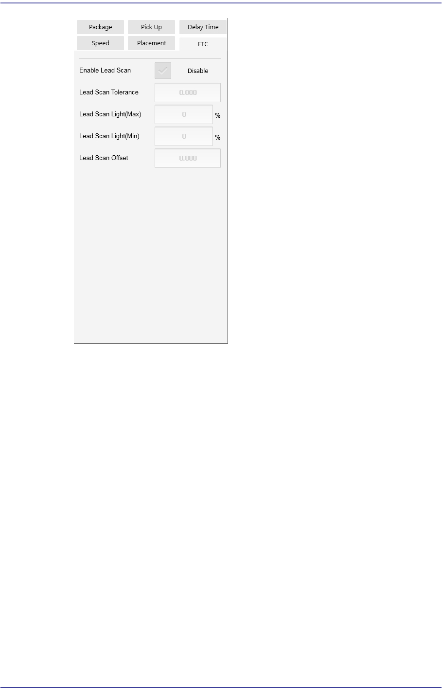
<Enable lead scan> check button
Selected when inspecting the leads of an IC part. This function can be used only
for machines equipped with a lead scanner.
<Lead Scan Tolerance> edit box
Input the value that allows the extent by which a lead deviates from the normal
pattern. It is indicated in mm. If the difference in the height of two neighboring
leads is greater than this value or a specific lead deviates from this value when it is
assumed that the inclination of each lead is straight line, the corresponding part is
judged to be defective.
<Lead Scan Gain> edit box
Sets the gain of the light receiving section for the laser spot beam. In general, set
this value to '2'.
<Lead Scan Offset> edit box
Even if it is possible to input and use an offset at the position calculated for lead
scanning, generally set it to '0'.
<Lead Scan Test> button
Performs a lead scan test.
8-1
Feeder Setup
Chapter8. Feeder Setup
8.1. Feeder [F4]
The ‘Feeder’ submenu edits data related to tape feeder, stick feeder, and tray feeder. The
user can specify the part to be installed on each feeder, teach the pick-up position, and test
the component pick-up. When this submenu is selected, the initial screen is for the tape
feeder screen.
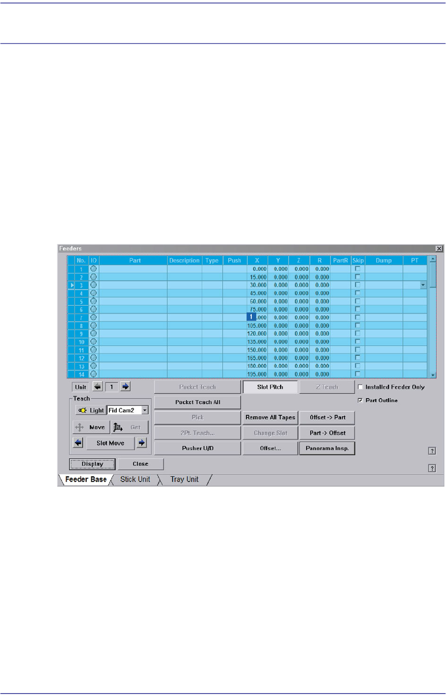
8.1.1. Feeder Base
When the feeder base is selected, the following dialog box is displayed and the data on
feeder base can be edited.
Figure8.1 “Feeder: Feeder Base” dialog box
1: Grid
‘Grid’ group
Display the status of various devices installed on the feeder base including the feeder
type and edit the installation position.
<No> column
A serial number of the feeder base slot. Air pressure type feeder base has 52 slots.
<IO> column
Displays the LED color for the status of the tape feeder installed in the
corresponding slot.