Hanwha SM481 PLUS Series Administrator’s Guide Eng.pdf.pdf - 第419页
14-67 Machine Calibration 9. The calibration is p e rformed automatically . If it is completed, the calibration result is displayed as shown in the following figure. Click the <Next> button . 10. Then the message “…
14-66
Fast Flexible Placer SM481(L) PLUS Administrator’s Guide
5. The message “Move To Center Position of [Fix1] Camera. To Move, Click [Next]”
appears. Click the <Next> button to move the corresponding head to the center of the
Fix1-camera. At this time, select the ‘Fix1 Cam’ in the <Target Camera> combo box.
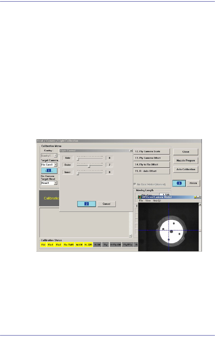
Click the <Light…> button and adjust the brightness of the light in the ‘Light Control’
dialog box so that the fiducial mark on the CNT20 nozzle that is seen in the
‘SMVision’ window can be seen clearly.
6. Then the message “Align Tool for Calibration! Then Click [Next]” appears. Click the
<Next> button.
7. Then the message “Up to Align Height and Mirror Close, Click [Next]” appears. Click
the <Next> button.
8. Then, the Head1 Pick the Calibration Tool and Z-axis of the Head 1 moves up to the
‘part-alignment height’ of the fly camera and the mirror is closed. and the message
“Calibration is Prepared. To Calibrate, Click [Next]” appears in the message box. At
this time, select the ‘Fly1 Cam’ in the <Target Camera> combo box. Click the
<Light…> button and adjust the brightness of the light in the ‘Light Control’ dialog
box so that the fiducial mark on the calibration tool that is seen in the ‘SMVision’
window can be seen clearly. Then click the <Next> button.
14-67
Machine Calibration
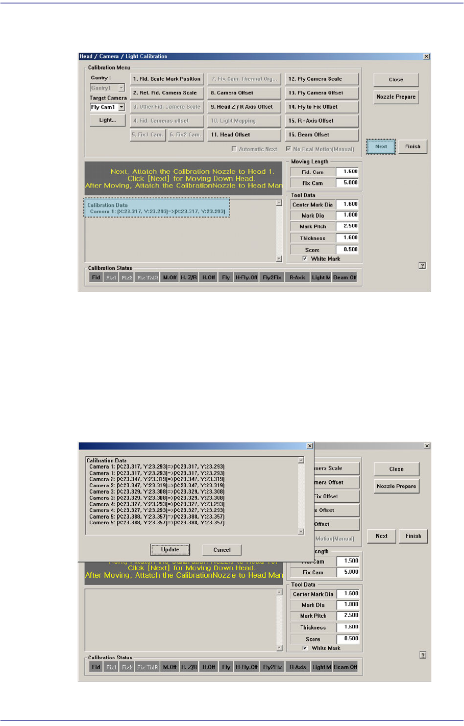
9. The calibration is performed automatically. If it is completed, the calibration result is
displayed as shown in the following figure. Click the <Next> button.
10. Then the message “Next, Remove the Calibration Nozzle From Head 1. Click [Next]
for Moving Down Head. After Moving, Remove the Nozzle Manually” appears. Click
the <Next> button to remove the CNT20 nozzle from the nozzle-holder of Head #1
manually.
11. Form Fly-Camera #2 to Fly-Camera #10, perform calibration in the same manner as it
was performed for Fly-Camera #1.
If the calibration procedure is completed for all fly-cameras normally, the result is
displayed as shown in the following figure.
14-68
Fast Flexible Placer SM481(L) PLUS Administrator’s Guide
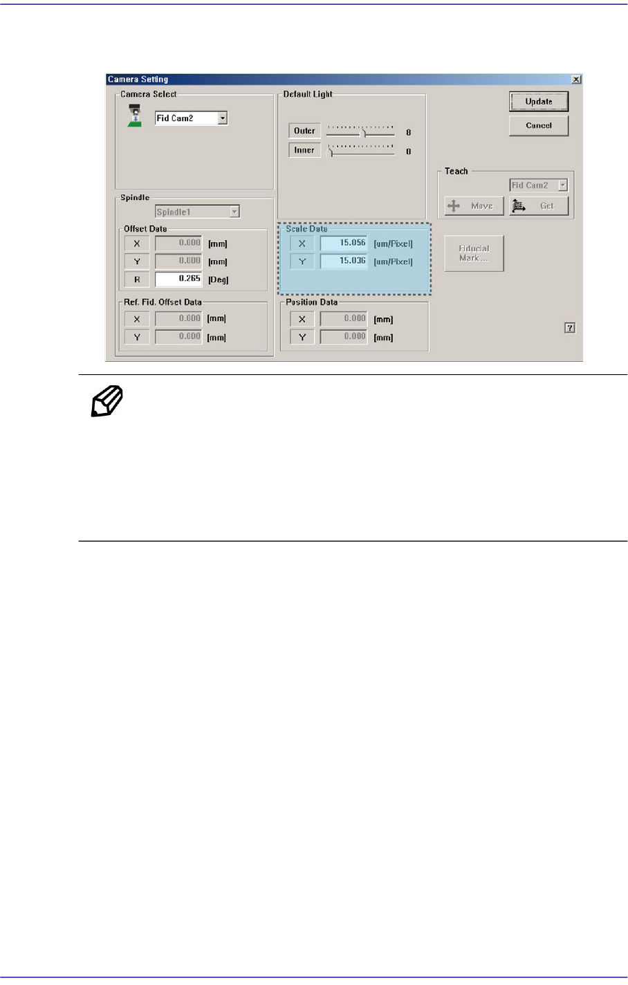
12. The result value can be confirmed in the Camera dialog box in the System Setup
menu.
Memo The range of the reference values for the ‘fly-camera calibration’ is as
follows:.
FOV 25 (MEGA)
ScaleX: 22.85~23.81 (μm/pixel)
ScaleY: 22.85~23.81 (μm/pixel)