Hanwha SM481 PLUS Series Administrator’s Guide Eng.pdf.pdf - 第227页
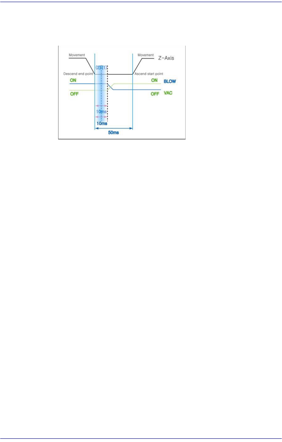
7-69 Part Registration <V ac Off> e di t box During component placement, the d e lay time after the head spindle has come down until vacuum is of f . For example, if the ‘Place’, ‘V ac OFF’ a nd ‘Blow ON’ are set…
7-68
Fast Flexible Placer SM481(L) PLUS Administrator’s Guide
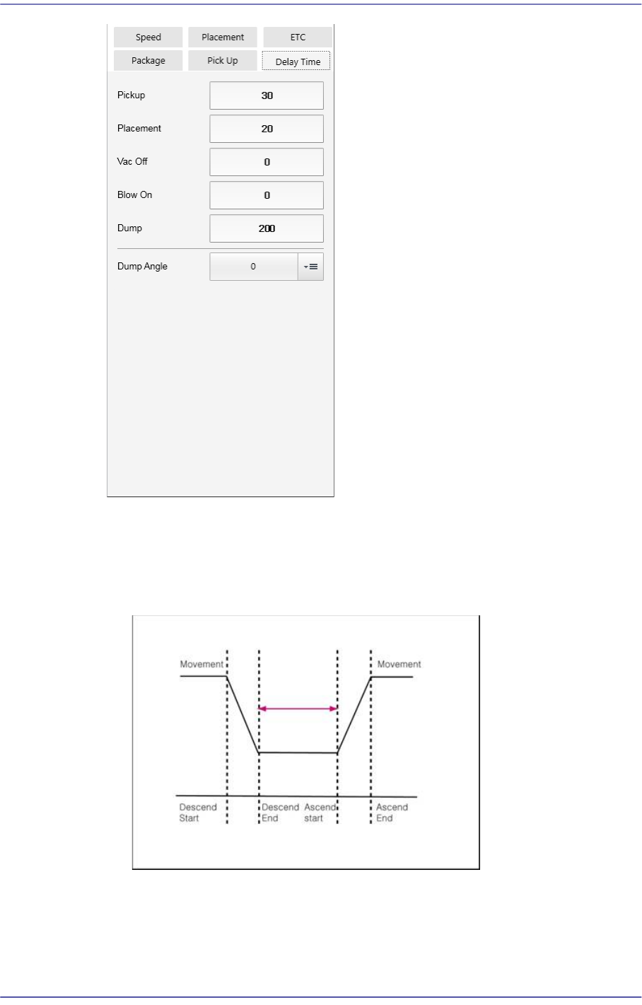
<Pickup> edit box
Input the time from when the head spindle has stopped after moving down for part
pickup until it starts to move up.
The following is the 'Pickup Delay Time’ Sequence Diagram.
<Placement> edit box
Input the time from when the head spindle has stopped after moving down for part
placement until it starts to move up.
7-69
Part Registration
<Vac Off> edit box
During component placement, the delay time after the head spindle has come
down until vacuum is off.
For example, if the ‘Place’, ‘Vac OFF’ and ‘Blow ON’ are set to 50, 10 and 10
respectively,
The time required is 50ms from the time the Z axis finishes moving down for
placement until the Z axis begins to move up after all processes are completed.
The ‘Vac off’ 10 means that the vacuum will be turned off in 10ms after the Z
axis finishes moving down for placement.
The ‘Blow ON’ 10 refers to the delay time from the time the Z axis finishes
moving down to the time the Blow On is performed.
7-70
Fast Flexible Placer SM481(L) PLUS Administrator’s Guide
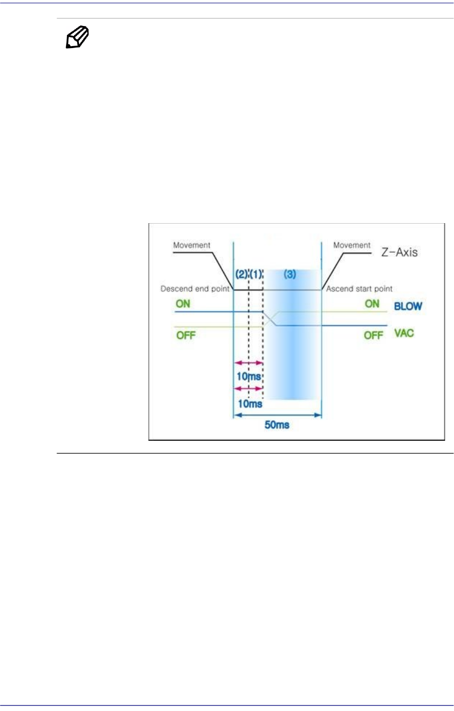
Memo Normally, the type of the time graph becomes different by parts.
For example, in the case of the general rectangular chips greater
than 1608, the parts are very light. Therefore, if the Z-axis moves
up before the vacuum disappears completely, the part may fall to
the PCB when the vacuum disappears while it moves up along
with the head.
In other words, item (3) in the following figure may act as the most
important factor for general rectangular chips.
From many test and experiment results, it was known that the
required time in item (3) was at least 0ms up to 20ms. Since this is
very important, the user must have this in mind.