Hanwha SM481 PLUS Series Administrator’s Guide Eng.pdf.pdf - 第439页
15-3 System Setup <Board Release> o ption button group <Quick Load> option button Click this button to minimize the time b e tween PCB departures and a rrivals. This feature instructs the transport rail t…
15-2
Fast Flexible Placer SM481(L) PLUS Administrator’s Guide
15.1. Conveyor [F3]
Sets the conveyor related items.
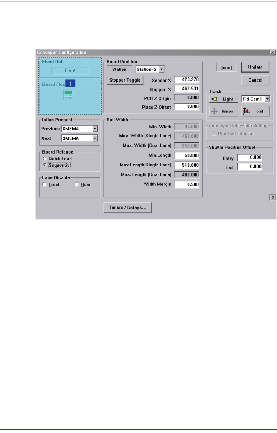
Figure15.3 “Conveyor Configuration” dialog box
1: Current Define
‘Current Define’ group
Displays the setup status of the current conveyor.
<Fixed Rail> group
Displays type of conveyor fixing (front/rear).
<Board Flow> group
Displays the direction of the conveyor board (right->left/ left->right).
<Inline protocol> group
Select the in-line protocol for the previous and next equipment from the Combo Box.
Stand alone: Operates the equipment separately without performing line operation.
Busy input only: Uses the protocol specified by the company which developed the
equipment as a communication protocol between the previous and next equipment
when performing line operation.
SMEMA: Uses the SMEMA protocol as a communication protocol between the
previous and next equipment when performing line operation.
15-3
System Setup
<Board Release> option button group
<Quick Load> option button
Click this button to minimize the time between PCB departures and arrivals. This
feature instructs the transport rail to acquire a new PCB immediately after the
machine release the current PCB.
<Sequential> option button
Click this button to instruct the transport rail that a PCB departing the downstream
station must exit completely before allowing the next PCB to enter.
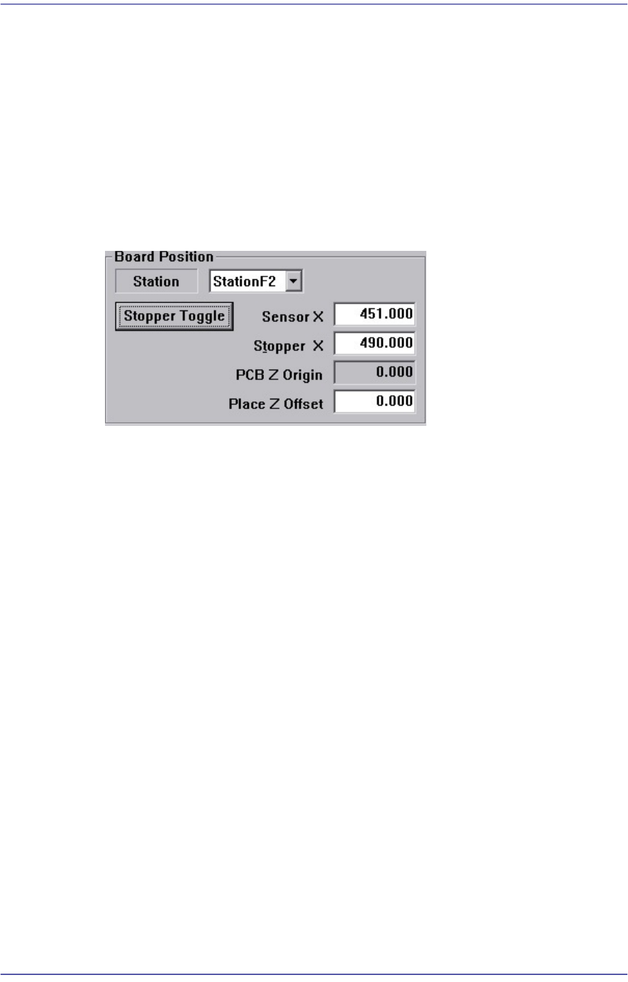
<Board Position> group
<Station> combo box
Select Working Station.
<Sensor X> edit box
Set the coordinate of the PCB detection sensor at the selected station.
<Stopper X> edit box
Set the coordinate of the stopper at the selected station.
<PCB Z Origin> edit box
Displays the calibration value to be used to calibrate the difference between the
top surface of the ANC and the top surface of the PCB.
<Place Z Offset> edit box
Used to place the part by pressing the part in the Z axis direction as much as the
offset that was set here.
<Stopper Toggle> button
It is used to move the stopper up or down when teaching the stopper position.
<Rail Width> group
Sets the data related to the conveyor width adjustment.
Min. Width
Shows the minimum width of Transport rail.

15-4
Fast Flexible Placer SM481(L) PLUS Administrator’s Guide
Min. Length
Shows the minimum length of Transport rail.
Max. Width
Shows the maximum width of transport rail for each case of Single-Lane and Dual
Lane
Max. Length
Indicate the maximum PCB length that can be worked on each case of Single-
Lane and Dual Lane.
<Width Margin> edit box
When changing the conveyor width, widen it wider as much as its margin.
Method of setting up the ‘Conveyor Width Origin’ is as follows;
1. Perform ‘conveyor home’ using the teaching box as in the following figure.
2. Measure the conveyor width (distance between conveyor frame) accurately
using measuring instrumentation, and input the value to the <Width Margin>
edit box.
3. Reflect the changed value by clicking on the <Update> button.
4. Measure and input the Y value of the PCB to be tested into the <Board Size>
area of ‘Board’ dialog box, and fit the conveyor width to the entered Y value
by clicking on the <Conv. Width> button.
Check if there is any foreign material on the conveyor, and remove if any.
5. Check if the test PCB is normally transported to the placement position and
gets out of the conveyor by clicking on the <PCB In> button and <PCB Out>
button. In case of any problem, perform setup again from the beginning.
6. Default value is used for ‘Width Margin’, but it can also be changed by the
user. The margin between the conveyor and belt of this equipment is
approximately 2mm. Therefore, when the entered ‘Width Margin’ is larger
than 1mm, the PCB may get curved.
<Timers/Delays> button
Displays the Timers/Delays dialog box, where the Transport related Timers and
Delays can be set.