Hanwha SM481 PLUS Series Administrator’s Guide Eng.pdf.pdf - 第494页
16-8 Fast Flexible Placer SM481(L) PLUS Administ r ator’s Guide 16.4. Vacu um [F5] Checks the air pressure status of the he ad. Figure16.7 “Vac uum Diagnosis” dialog box <Head V acuum level> group Displays the va…

16-7
Diagnosis
follows.
<Outer>: The range of the Outer light level is 0~15.
<Inner>: The range of the Inner light level is 0~15.
When the fly camera is selected, the range of light level that can be set is as follows.
<Side>: The range of the side light level is 0~15.
<Outer>: The range of the Outer light level is 0~15.
<Coaxial>: The range of the Coaxial light level is 0~15.
When the fix camera is selected, the range of light level that can be set is as follows.
<Side>: The range of the side light level is 0~15.
<Outer>: The range of the Outer light level is 0~15.
<Inner>: The range of the Inner light level is 0~15.
<Close> button
Closes the dialog box.
16-8
Fast Flexible Placer SM481(L) PLUS Administrator’s Guide
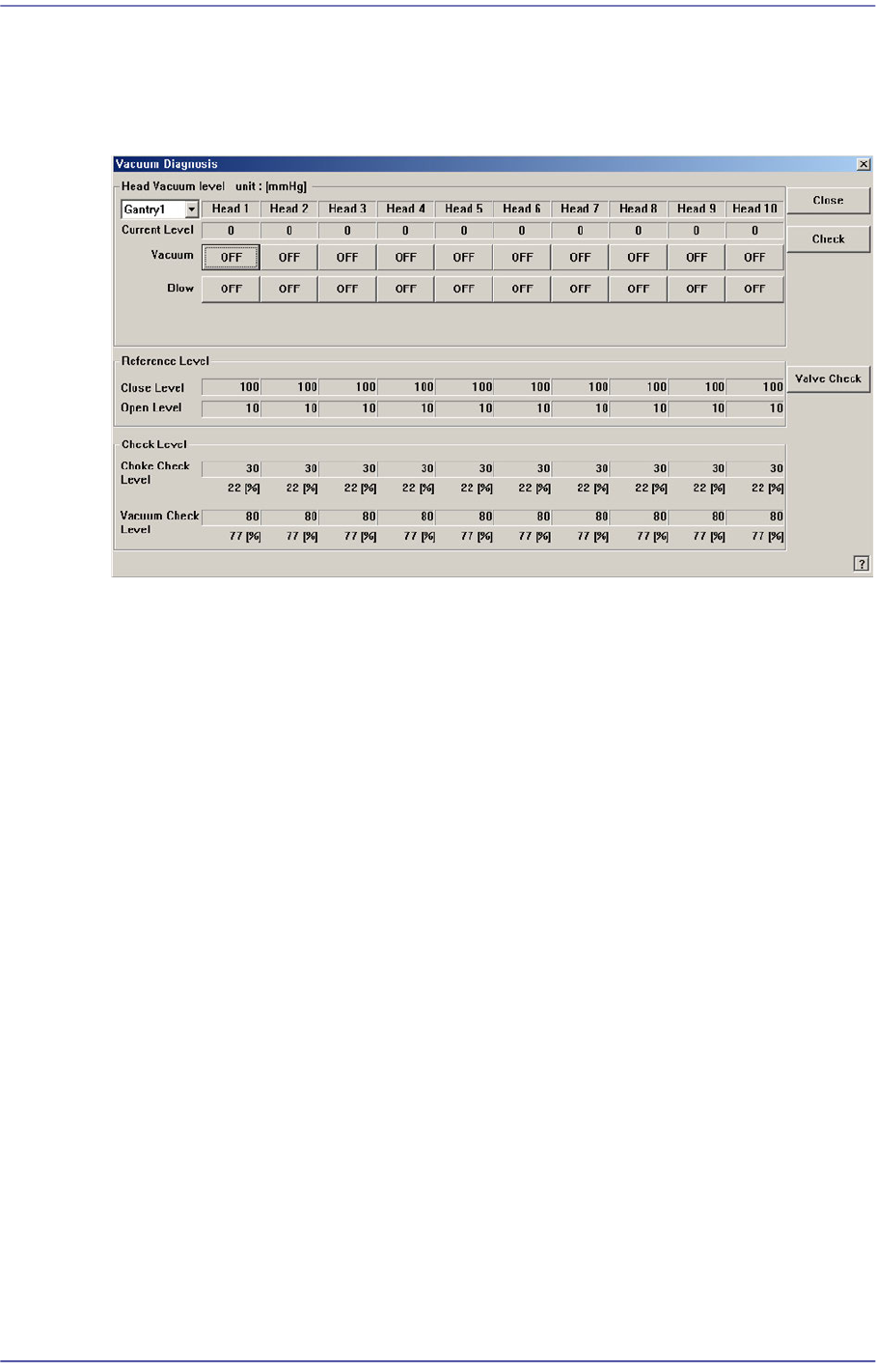
16.4. Vacuum [F5]
Checks the air pressure status of the head.
Figure16.7 “Vacuum Diagnosis” dialog box
<Head Vacuum level> group
Displays the vacuum level of each head and controls the vacuum generator.
<Gantry> combo box
Select the gantry for which the pneumatic pressure can be checked.
<Current Level>
Indicate the current pneumatic pressure of each head.
<Vacuum OFF> button
Pressing this button when “OFF” is indicated will supply constant pneumatic
pressure of 0.1Mpa inside the spindle and indicate “ON” on the button.
<Blow OFF> button
Pressing this button when “On” is indicated will shut off the pneumatic pressure
supplied to the spindle and indicate “OFF” on the button.
<Reference Level> group
When the vacuum level is used as a criteria for determining the component pick-up by
each head, displays the standard value.
<Close Level>
Indicate the pneumatic pressure of each head when the nozzle hole is plugged,
with the nozzle being inserted into the nozzle holder.
<Open Level>
Indicate the vacuum value of each head when the nozzle hole is opened, with the
16-9
Diagnosis
nozzle being inserted into the nozzle holder.
<Check Level > group
Displays the vacuum level that is used as a criteria for determining the component
pick-up.
<Choke Check Level>
Displays the vacuum level that considers the nozzle to be choked up before the
component pick-up.
<Vacuum Check Level>
Displays the vacuum level that considers a pickups to be successful after the
component pick-up.
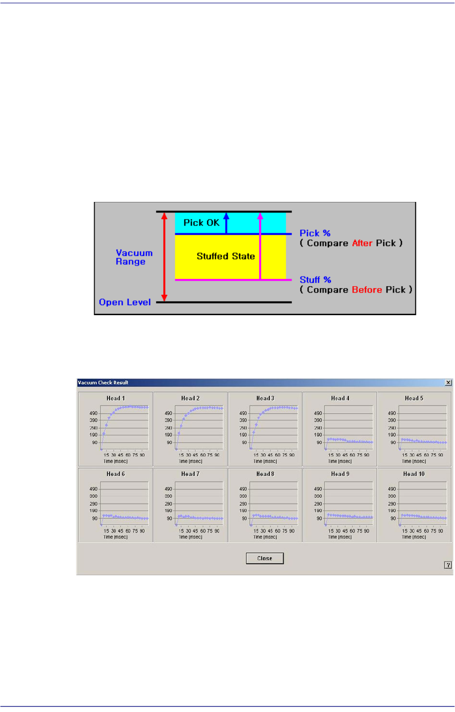
<Check> button
Measure the time that it takes until the vacuum value becomes stabilized for all heads
of the selected gantry.
<Valve Check> button
Check the solenoid valve to find that the ‘Vacuum On’ and ‘Blow Off’ are executed
properly. Insert the CN40 nozzle in the head spindle’s nozzle holder manually and
check the valve.
The following dialog box shows the results of the solenoid valve checks using the
CN040 nozzle.