Hanwha SM481 PLUS Series Administrator’s Guide Eng.pdf.pdf - 第432页
14-80 Fast Flexible Placer SM481(L) PLUS Administ r ator’s Guide 14.3.8. Board Positon Calibration T each the stopper position in the conveyor installa tion area and the X position of the sensor . The following is the bo…
14-79
Machine Calibration
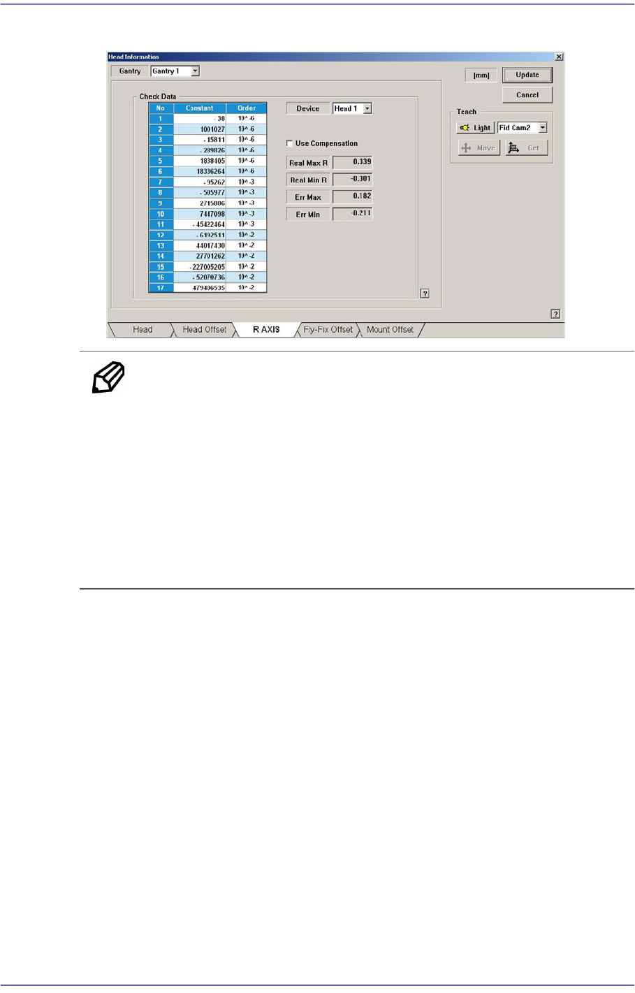
11. The measurement result can be confirmed in the R Axis dialog box.
Memo The reference values for the calibration of the R-Axis Offset is as
follows.
Real Max(Min): The Max.(Min.) offset between command value
and calibration value
Head1~Head10 : -1.000 ~ 1.000(deg)
Err Max(Min) The Max.(Min.) offset between compensation
value and calibration value
Head1~Head10 : -0.300 ~ 0.300(deg)
14-80
Fast Flexible Placer SM481(L) PLUS Administrator’s Guide
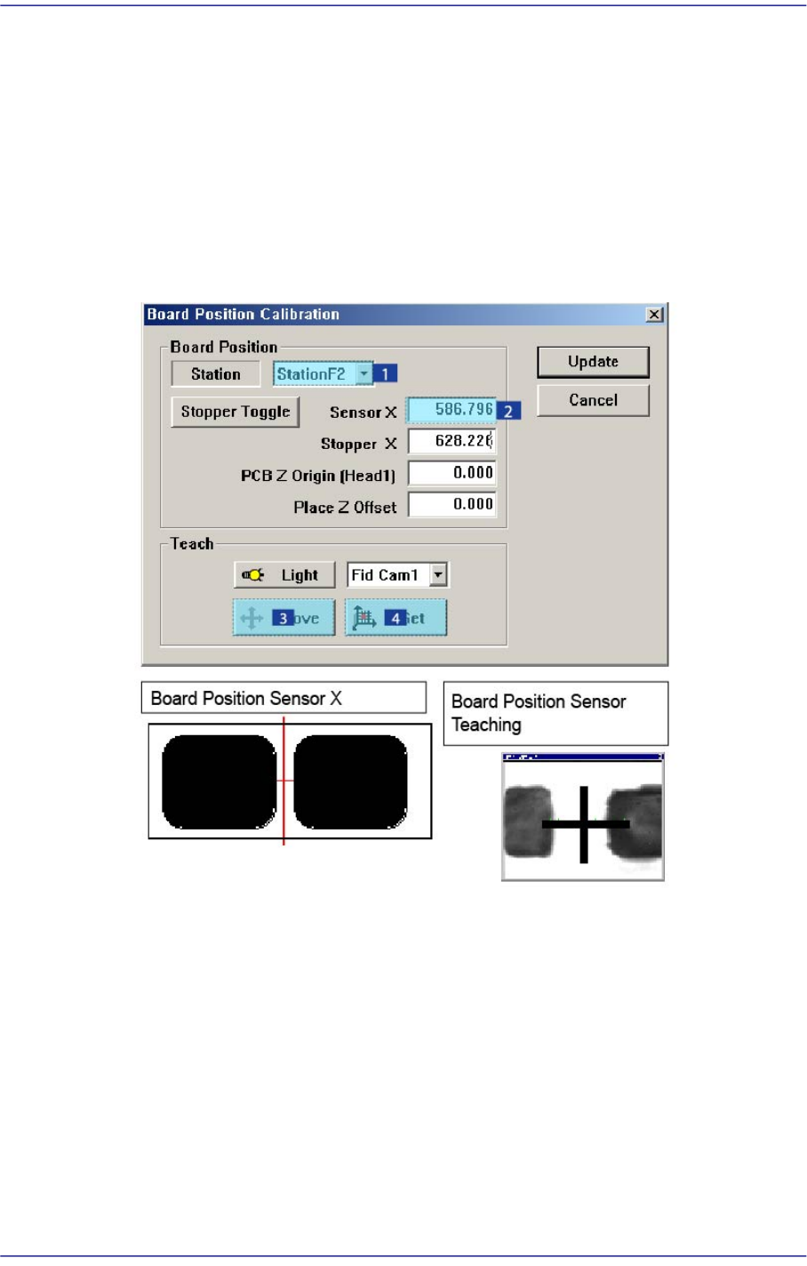
14.3.8. Board Positon Calibration
Teach the stopper position in the conveyor installation area and the X position of the
sensor.
The following is the board position calibration procedure.
1. Select the < Sensor X> edit box using the mouse and move the Fiducial Camera to the
position of Sensor X by clicking the <Move> button.
2. Perform teaching of the exact position using the teaching box. Enter the precise
coordinates for ‘Sensor X’ by pressing the <Get> button of the teaching box.
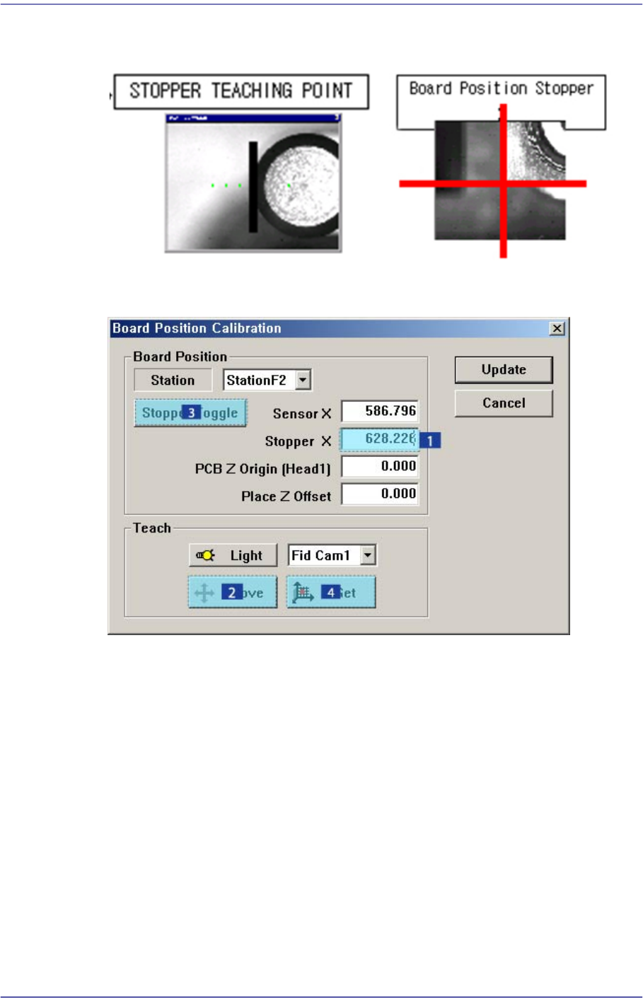
3. Select the < Stopper X> edit box using the mouse and move the Fiducial Camera to the
position of Stopper X by clicking the <Move> button.
4. Click the <Stopper Toggle> button in the left of the <Stopper X> edit box first to move
the stopper up and then teach the stopper position correctly using the teaching box.
5. Click the <Get> button to enter the coordinates in the <Stopper X> edit box.
14-81
Machine Calibration
6. Click the <Stopper Toggle> button to move down the stopper.
7. Save the data by clicking the <Update> button.
[Additional calibration that must be performed in the SM481L machine]
When using the long conveyor option of 1500mm in length and 460mm in width for two-
staged placement, the calibration for Station 3 must be performed additionally. (When a
PCB moves from the right to the left on the conveyor, perform calibration of Station 1
additionally.)
1. Load a PCB to Station 3 area and align the steel ruler with the PCB end as shown in
the following figure: