Hanwha SM481 PLUS Series Administrator’s Guide Eng.pdf.pdf - 第195页
7-37 Part Registration selected object is rectangular is this enabled. Mark Edits a direction mark shape to a defined ob ject or deletes it. The following shows the Flip Check. 1: Sets Brightness / Differ ence <T …
7-36
Fast Flexible Placer SM481(L) PLUS Administrator’s Guide
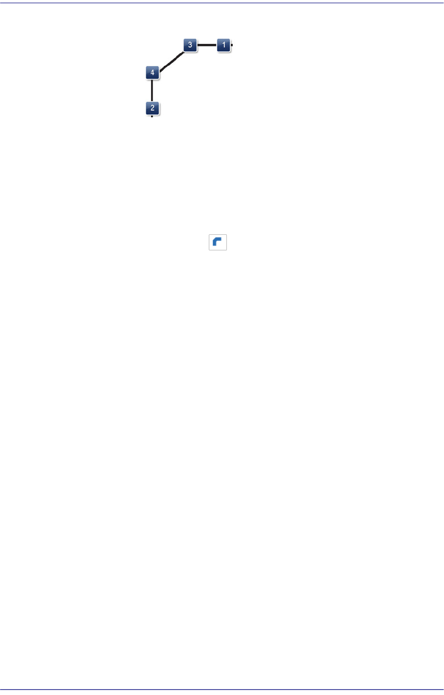
1: Length of the corner in the X direction
2: Length of the corner in the Y direction
3: X gap for bending start
4: Y gap for bending start
<Gap XY> edit box
Enabled only when the is selected in the <Shape> group. Input the size of
the corner in the X and Y directions.
<Algorithm> combo box
Selects the vision algorithm to be used to perform the corner check.
Fine
Selected in cases to recognizes the boundary of the corner precisely. It is
recommended that this method be selected.
Rough
Selected when the value for the boundary of the corner is not checked. It is
not recommended that this method be selected.
<Score> edit box
The “Score” is the numerical value that indicates how accurately the part
shape recognized by the vision system matches with the registered corner
object data. This “Score” has a value between 0 and 1000 points.
<Position> check button
Of the four corners of the corner parts, select the section corresponding to the
shape selected from the <Shape> group.
The vision parameter related to the corner is applied to the section selected
here.
<Width> edit box
Input the width of an object to suit the image of an actual part. If the selected
object is round, input the diameter.
<High> edit box
Input the height of an object to suit the image of an actual part. Only when the
7-37
Part Registration
selected object is rectangular is this enabled.
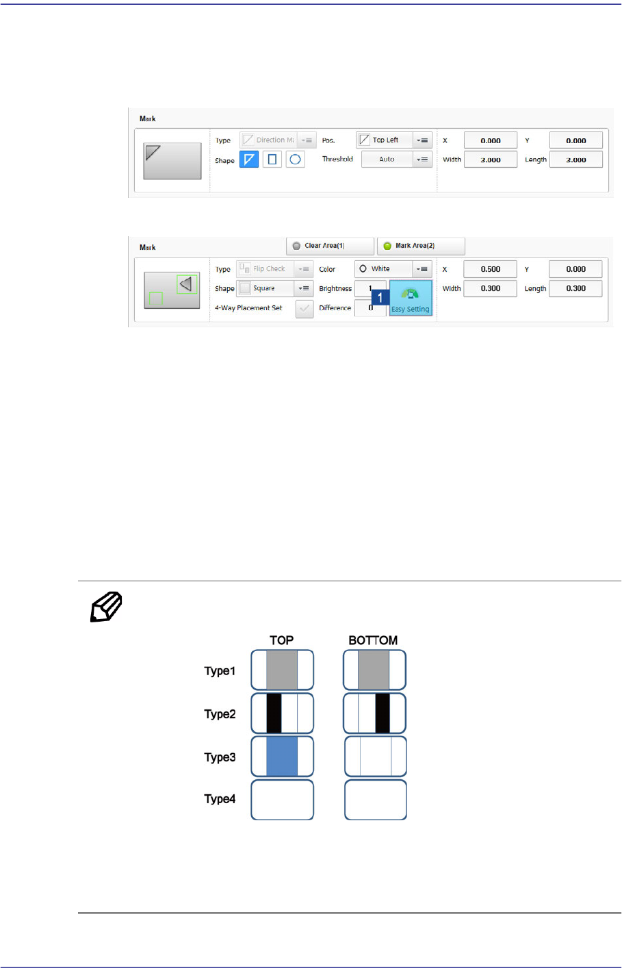
Mark
Edits a direction mark shape to a defined object or deletes it.
The following shows the Flip Check.
1: Sets Brightness / Difference
<Type> combo box
Select the direction mark type to edit.
Direction Mark
Selected when a user edits the mark displaying the direction of IC and
BGA.
Flip Check
Selected when a user edits the mark to divide the top surface and bottom
surface of the Chip R and LED.
Memo In the following cases, the 'Flip Check' function cannot be used.
When the top and bottom surface shapes of the part are the same
When the image of the top and bottom surfaces is not contrasted
clearly
7-38
Fast Flexible Placer SM481(L) PLUS Administrator’s Guide
<Shape> group
When the 'Direction Mark' is selected as a direction mark type
Select the direction mark shape. (triangle, rectangle, circle)
- Shape definition - Mark (Direction Mark)
1: Position change of the selected point (Up - Down)
2: Position change of the selected point (Left - Right)
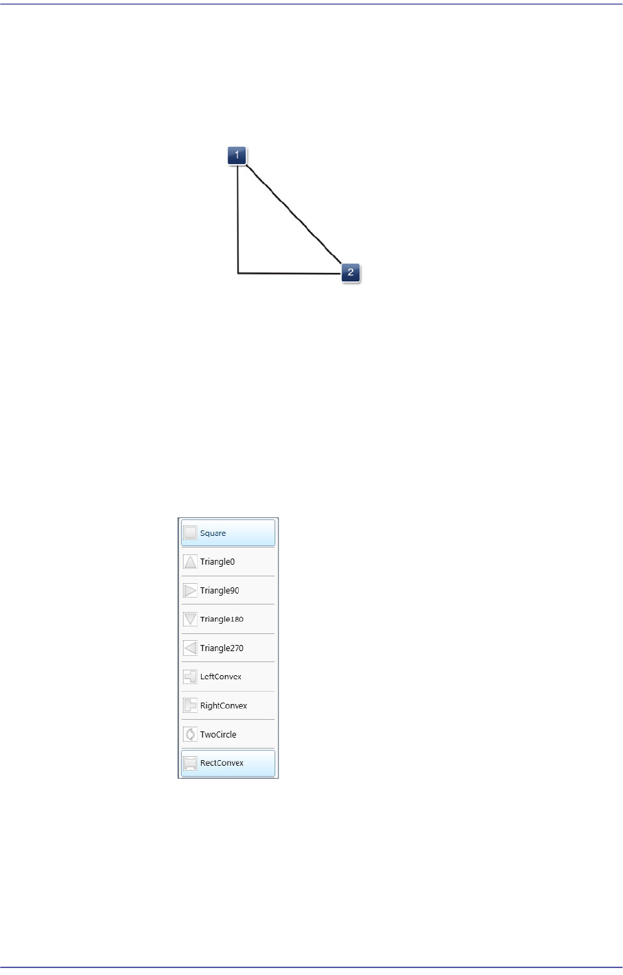
When the 'Flip Check' is selected as a direction mark type
Displayed when the <Mark Area (2)> switch button is selected.
Selects a shape to the mark or convex-concave on the bottom surface of
the LED. If the convex-concave shape is selected, the brightness of the
selected area as well as the direction of a protrusion are checked. This,
therefore, prevents the part from being placed upside down.
Square: There is no shape.
Triangle 0: Triangle mark in the 0° direction.
Triangle 90: Triangle mark in the 90° direction.
Triangle 180: Triangle mark in the 180° direction.
Triangle 270: Triangle mark in the 270° direction.
Left Convex: There is a recess or protrusion at the bottom surface of the