Hanwha SM481 PLUS Series Administrator’s Guide Eng.pdf.pdf - 第413页
14-61 Machine Calibration 4. Then the messag e “Next Att ach the Calibration T ool to Head 1. Click [ Ne xt] for Moving Down Head. A fter Moving, Attach the tool to head Manually” appears. Click the <Next> butt on …
14-60
Fast Flexible Placer SM481(L) PLUS Administrator’s Guide
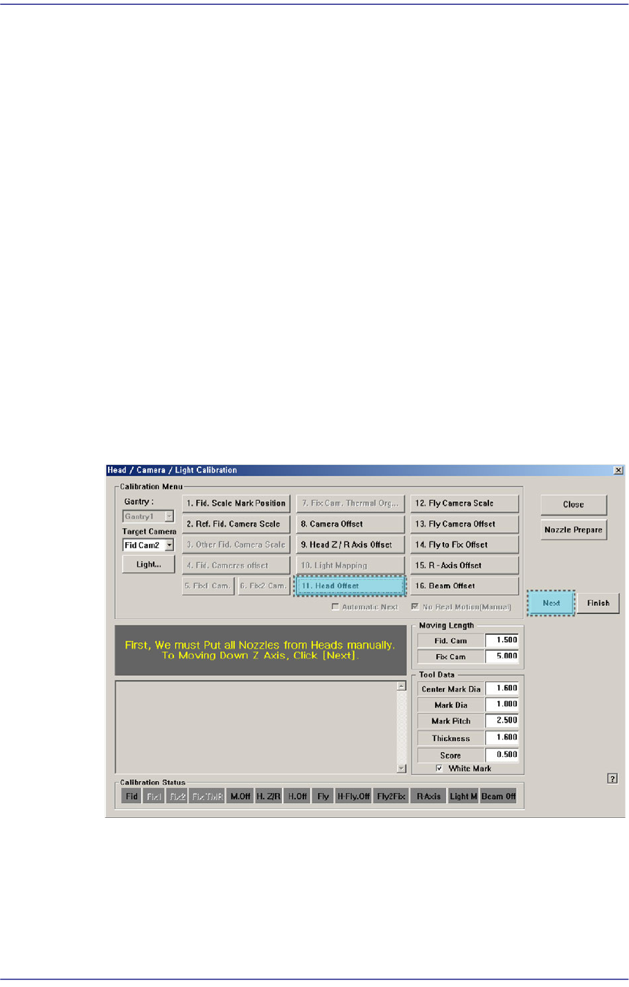
14.3.7.7. Head Offset Calibration
Measure the distance (XY Offset) between the center of the gantry fiducial camera and the
center of each head.
The following is the procedure to calibrate the XY offset of the head;
1. Click the <Nozzle Prepare> button and insert the CNT20 nozzle into the No. 1 hole of
the ANC manually.
2. If the <11. Head Offset> is clicked after selecting the <Automatic Next> check box,
calibration is performed for the selected gantry automatically.
If calibration is performed after selecting the <No Real Motion [Manual]> check box,
the nozzle is inserted into each head manually. Click the <Next> button to move onto
the next step.
If calibration is performed without selecting either the <Automatic Next> check box
or < No Real Motion [Manual]> check box, the nozzle is changed automatically for
the currently selected nozzle. Click the <Next> button to move onto the next step.
If the <11. Head Offset> button is clicked, the message “First, We must Put all
Nozzles From Heads Manually. To Moving Down Z Axis, Click [Next]” appears in
the message box. Click the <Next> button to move down the Z axis of the head in
order to remove all nozzles inserted in the nozzle-holder manually.
3. Then, after the head assembly moves to the designated position, move all Z-axes
down. At this time, remove all inserted nozzles manually.
14-61
Machine Calibration
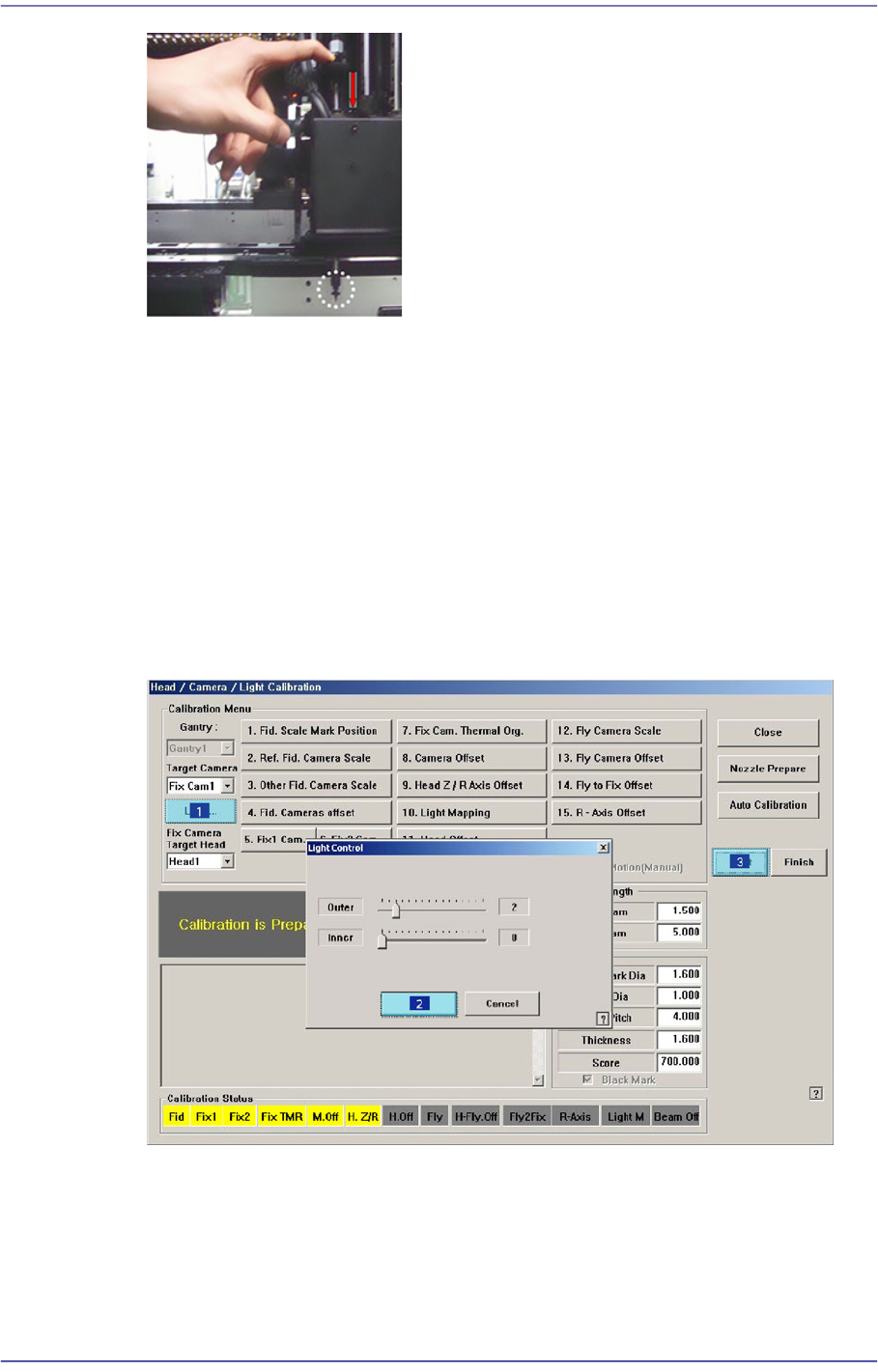
4. Then the message “Next Attach the Calibration Tool to Head 1. Click [Next] for
Moving Down Head. After Moving, Attach the tool to head Manually” appears. Click
the <Next> button after inserting the calibration tool in the CNT20 nozzle at nozzle-
holder of Head #1 manually.
5. The message, “Move To Center Position of [Fix 1] Camera. To Move, Click [Next]” is
displayed in the message window. Click the <Next> button to move the head assembly
to the center of the Fix 1 Camera.
6. The message “Calibration is Prepared. To Calibrate, Click [Next]” appears. At this
time, click the <Light…> button and adjust the brightness of the light in the ‘Light
Control’ dialog box so that the fiducial mark on the calibration tool that is seen in the
‘SMVision’ window can be seen clearly. Then click the <Next> button.
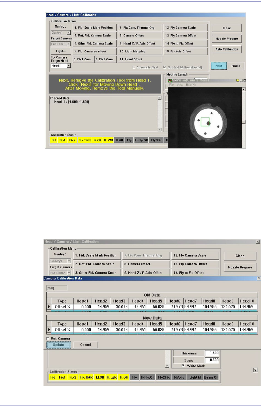
7. The calibration is performed automatically. If it is completed, the calibration result is
displayed as shown in the following figure. Click the <Next> button.
14-62
Fast Flexible Placer SM481(L) PLUS Administrator’s Guide
8. Then the message “Next, Remove the Calibration Nozzle From Head 1. Click [Next]
for Moving Down Head. After Moving, Remove the Nozzle Manually” appears. Click
the <Next> button to remove the calibration tool from the nozzle-holder of Head #1
manually.
9. Form Head #2 to Head #10, perform calibration in the same manner as it was
performed for Head #1.
10. If the calibration procedure is completed for all heads normally, the result is displayed
as shown in the following figure. Click the <Update> button to apply the calibration
value.