Hanwha SM481 PLUS Series Administrator’s Guide Eng.pdf.pdf - 第205页
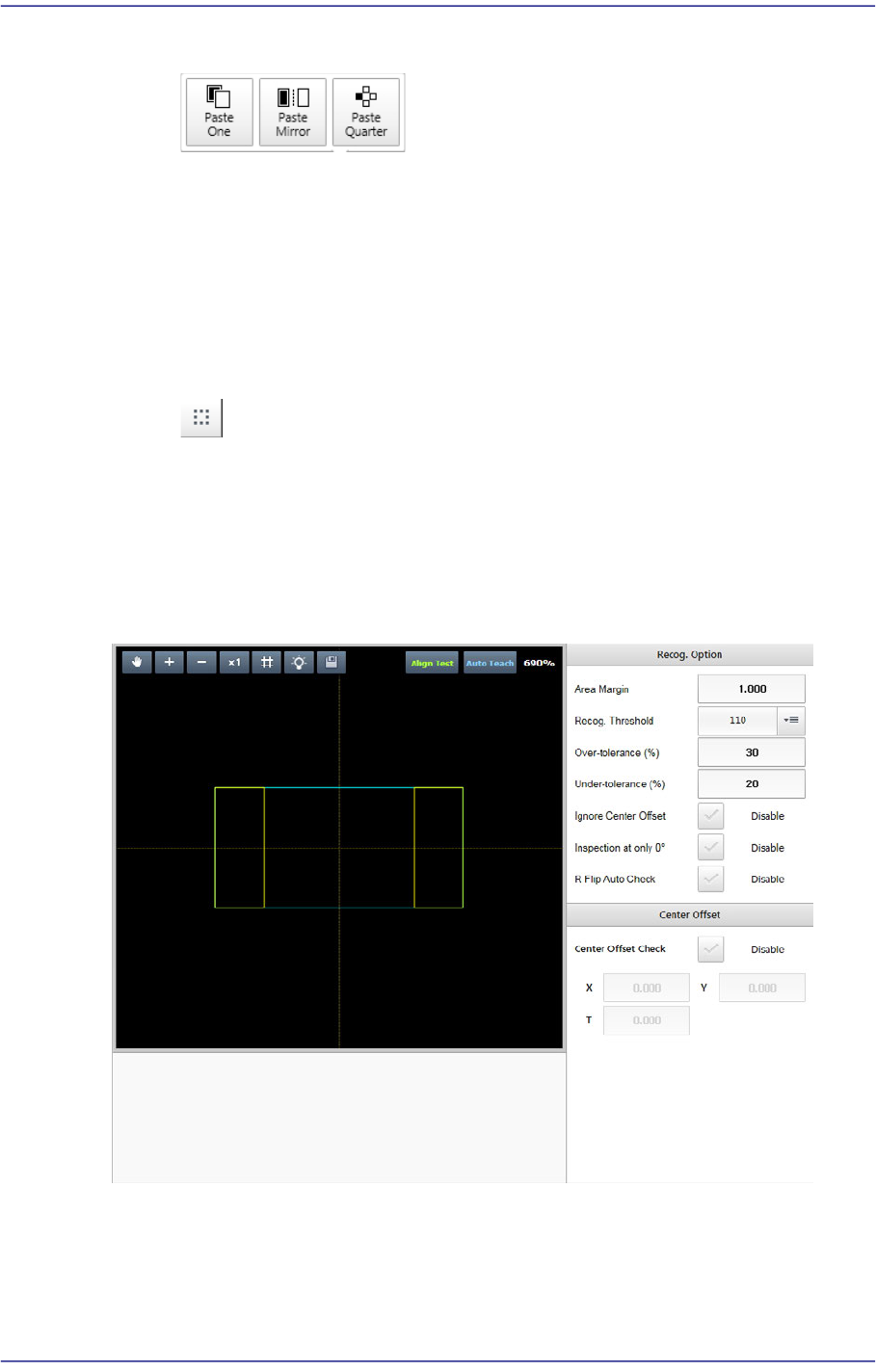
7-47 Part Registration Copies the object selected from th e <Object List> group. Past One Adds an objec t identical to the selected object. Paste Mirror Adds an objec t so that it will be symmetrical to the sel…
7-46
Fast Flexible Placer SM481(L) PLUS Administrator’s Guide
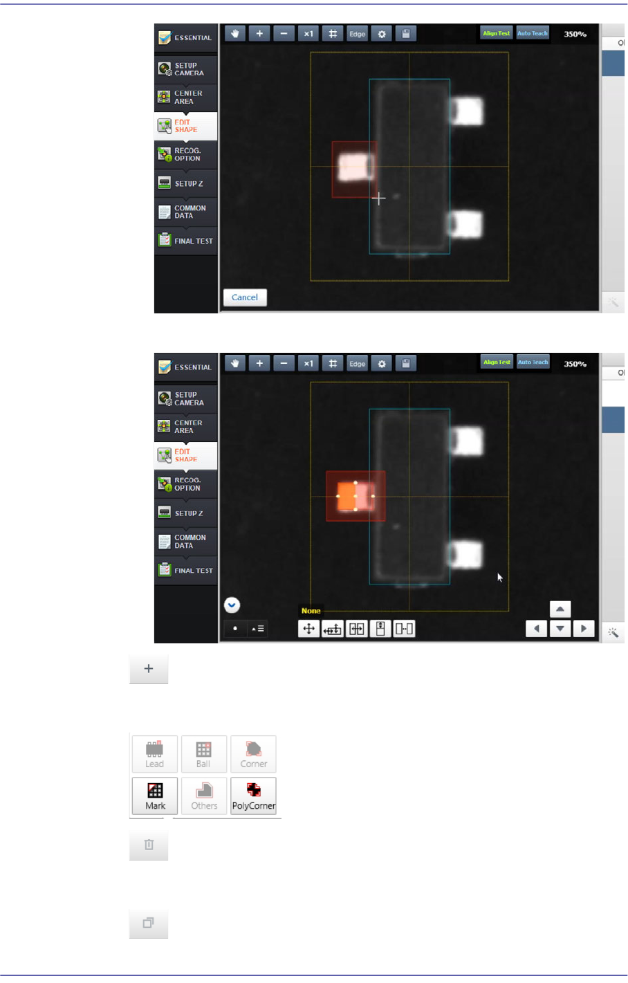
3) Create a shape object to be recognized partially and perform a recognition test
button
Adds a lead, ball, corner, mark and other shape objects manually.
button
Deletes the object selected from the <Object List> group.
button
7-47
Part Registration
Copies the object selected from the <Object List> group.
Past One
Adds an object identical to the selected object.
Paste Mirror
Adds an object so that it will be symmetrical to the selected object.
paste Quarter
Adds objects so that they will be symmetrical to each other in four directions.
button
Groups the objects selected from the <Object List> group.
7.2.2.5. RECOG. OPTION
Sets the option related parameters allowing a part to be recognized under various
conditions by part.
<Recog. Option> group
It is possible to set the recognition option applied to all parts.
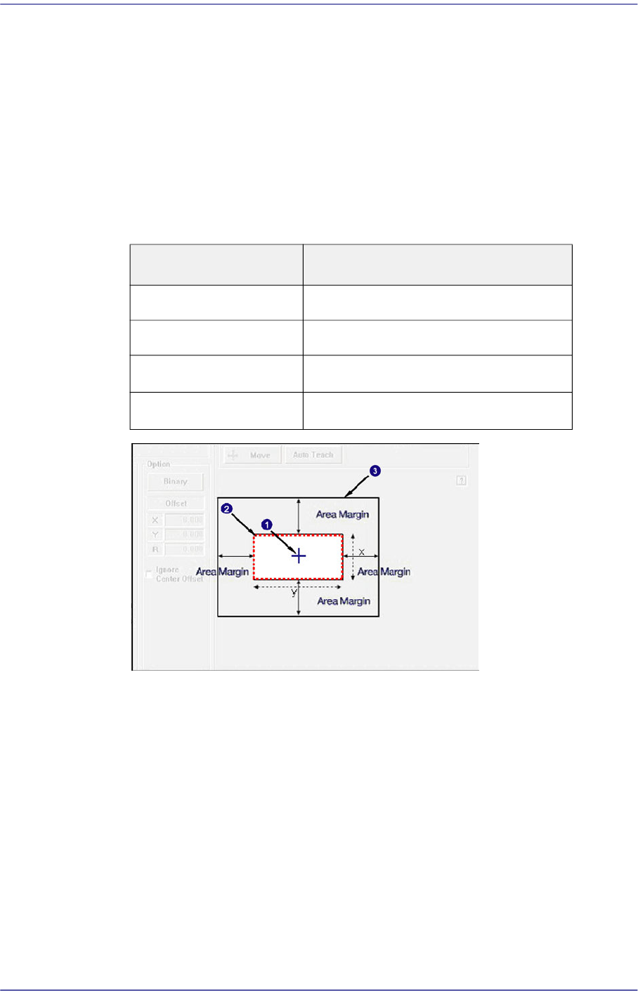
<Recognition Area Margin> edit box
7-48
Fast Flexible Placer SM481(L) PLUS Administrator’s Guide
If the area obtained by adding the 'Recognition Area Margin' to the part size is
called the ‘Part Recognition Area’, in normal cases the shape of the picked part
must be within the ‘Part Recognition Area’.
However, even though the shape of the picked part has gotten out of the ‘Part
Recognition Area’ due to other external factors, if the part can be placed properly
by compensating the extent of deviation, it is possible to place the corresponding
part properly by setting the 'Recognition Area Margin'.
In general, set a value within the range of 0~6. For a chip part, it is recommended
that the default value be used.
1: Center of Mechanism
2: Area with a Recognition Area Margin of '0'
3: Part Recognition Area
<Recog. Threshold> combo box
The image viewed through the vision window consists of each pixel. Each pixel
has its own value from 0~ 255 according to the degree of viewed brightness.
Here, the 'Threshold' signifies the boundary value that distinguishes whether to
recognize each pixel as white or black.
<Center Offset> group
<Center Offset check> check box
When it is not possible to set the part center as a pickup point, it is possible to set
Part Size Recognition Area Margin
0402~1608 0.750
2012~3216 1.500
3216~□5mm
2.000
□5mm~□10mm
3.000