Hanwha SM481 PLUS Series Administrator’s Guide Eng.pdf.pdf - 第305页
10-15 Opti mization 10.7. Op timization Result When the Optimizer execution is complet ed, the following dialog box is displayed. Figure10.7 “Opt imization Result” dial o g box This dialog box displays various results so…
10-14
Fast Flexible Placer SM481(L) PLUS Administrator’s Guide
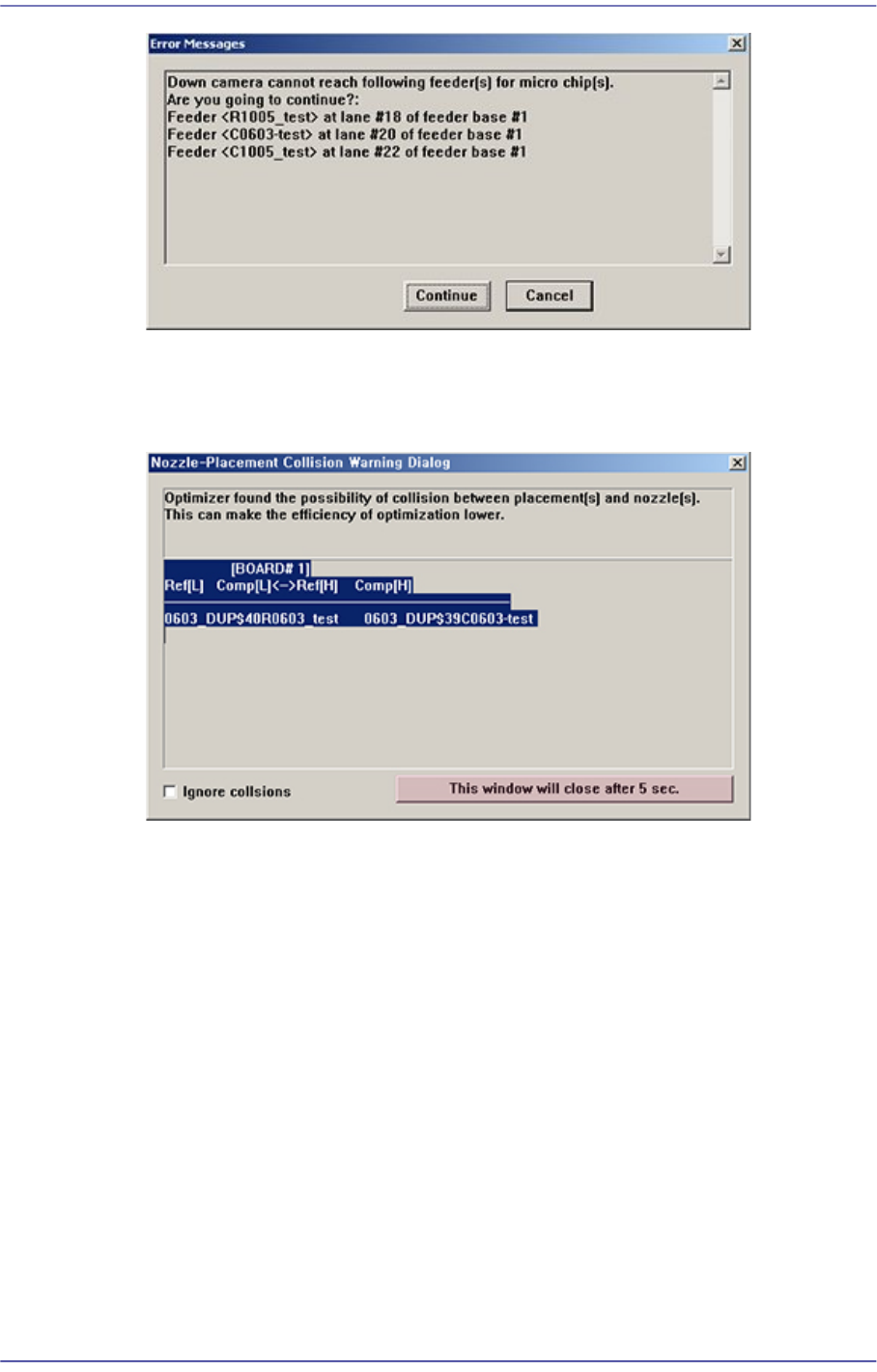
Message Type 2
Provides information to a user. However, it continues to execute the optimizer after a
certain period of time lapses regardless of the user’s input.
<Ignore collsions> check box
If this check box is checked, the parts are placed in the determined work sequence
by ignoring the collision that may occur between other parts already placed and
the nozzle during part placement.
<This window …> button
Click the button to exit the message box before the indicated time. Then the
message box exits immediately and the optimizer is executed continuously.
Message Type 3
Provides information to a user. However, the execution is stopped by the user’s input.
In most cases, it is indicated when an error occurred.
10-15
Optimization
10.7. Optimization Result
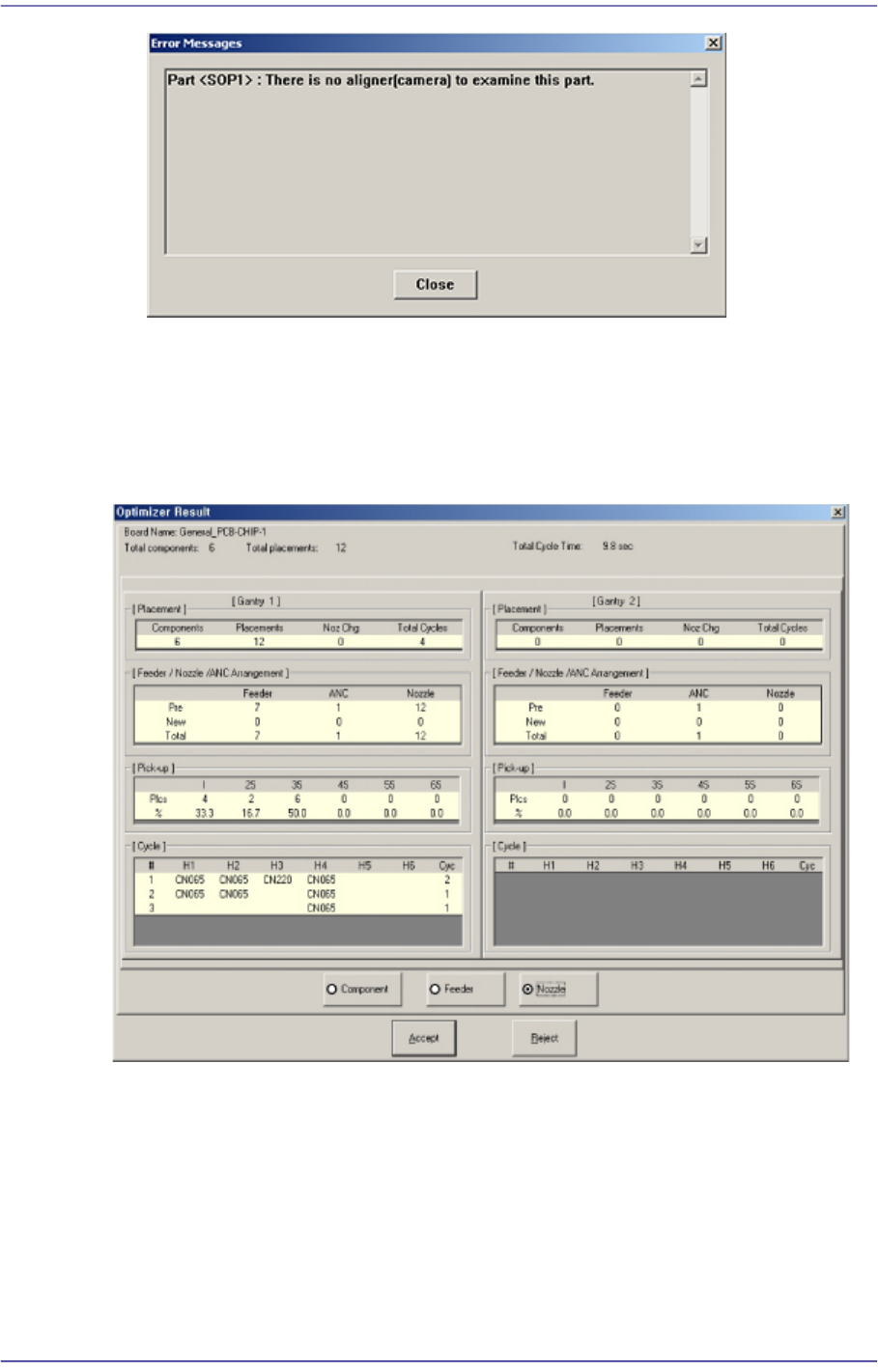
When the Optimizer execution is completed, the following dialog box is displayed.
Figure10.7 “Optimization Result” dialog box
This dialog box displays various results so that the optimized status can be viewed at a
glance.
When the <Accept> button is clicked on, this dialog box closes, the Optimizer is ended
and the result is applied to the MMI step program.
When the <Reject> button is clicked on, the result is not applied in the MMI step program.
If necessary, readjust the Optimizer options and execute again.

10-16
Fast Flexible Placer SM481(L) PLUS Administrator’s Guide
<Placement> group
Indicates the number of parts, number of total placement points, number of times of
nozzle replacement and total hours of working. The total working time is the estimated
time by simulation. It may be more or less different from actual pick and placement
time due to defective component recognition and other reasons.
<Feeder /Nozzle /ANC Arrangement> group
Indicates the arrangement status of tape feeder, ANC, and nozzles.
Pre: Number of tape feeders directly arranged by the user.
New: Number of tape feeders directly arranged by the optimizer.
Total: Total number of arranged tape feeders.
<Pickup> group
The distribution of simultaneous component pickups is displayed in this group. The
number of pickup points and its percentage for each pickup type is displayed in this
group.
I: Component pickups by one head only (individual pickup)
xS: x number of heads pick up components simultaneously
<Cycle> group
Indicates the final arrangement status of parts, feeders and nozzles of the step
program. Three radio buttons on the bottom let the user to select one and see the
allocation status. The number in the right most column displays the number of cycle
repetitions.
Component
In the component arrangement status, the component to be operated by each head
is displayed as cx, x is the number given to a component. (Component name is not
displayed here)
Feeder
In the feeder arrangement status, the feeder lane from which the head picks up is
displayed. The front feeder base is indicated by Fx, and the rear feeder base by Rx.
Here x is the feeder lane number. And, the stick feeder is indicated by Sx, and the
tray feeder by Tx.
Nozzle
The nozzle arrangement status shows which nozzle is used for which head. The
name of the nozzle to be attached to each head is displayed.