Hanwha SM481 PLUS Series Administrator’s Guide Eng.pdf.pdf - 第112页
6-2 Fast Flexible Placer SM481(L) PLUS Administ r ator’s Guide <1. Customer Name> e dit box Enter the name of the custom er who requested the PCB o pe ration . Up t o 64 characters can be en tered. <2. Board…
6-1
Board Definition
Chapter6. Board Definition
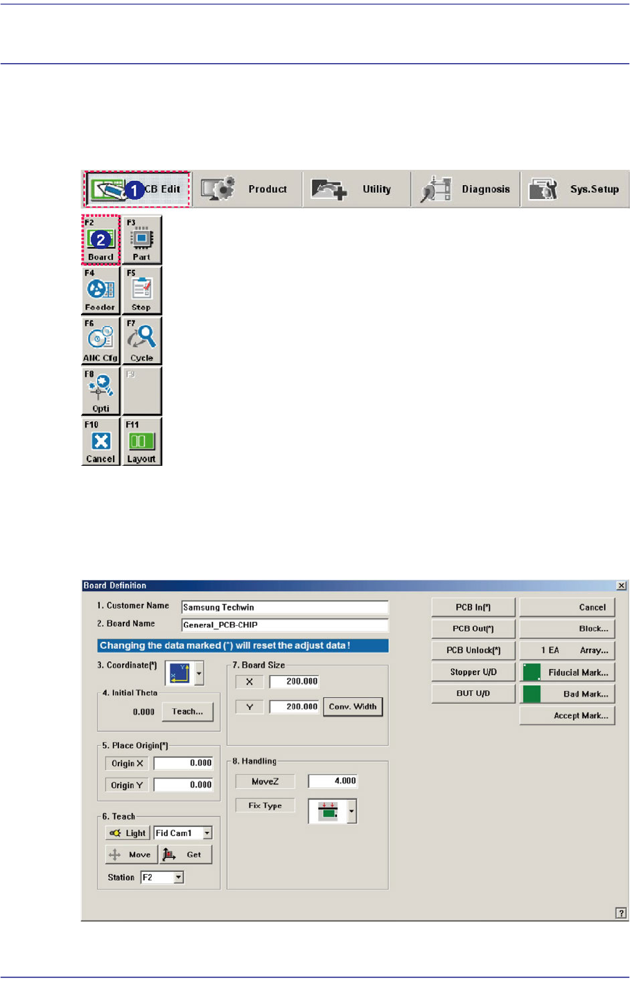
Used the ‘Board’ submenu to edit data for the placement of components on a PCB (Printed
Circuit Board).
Figure6.1 Sequence of executing board menu
6.1. Basic Setup
When the ‘Board’ submenu is selected, the following dialog box is displayed.
Figure6.2 “PCB Edit: Board Definition” dialog box
6-2
Fast Flexible Placer SM481(L) PLUS Administrator’s Guide
<1. Customer Name> edit box
Enter the name of the customer who requested the PCB operation. Up to 64 characters
can be entered.
<2. Board Name> edit box
Enter the PCB name. Up to 64 characters can be entered.
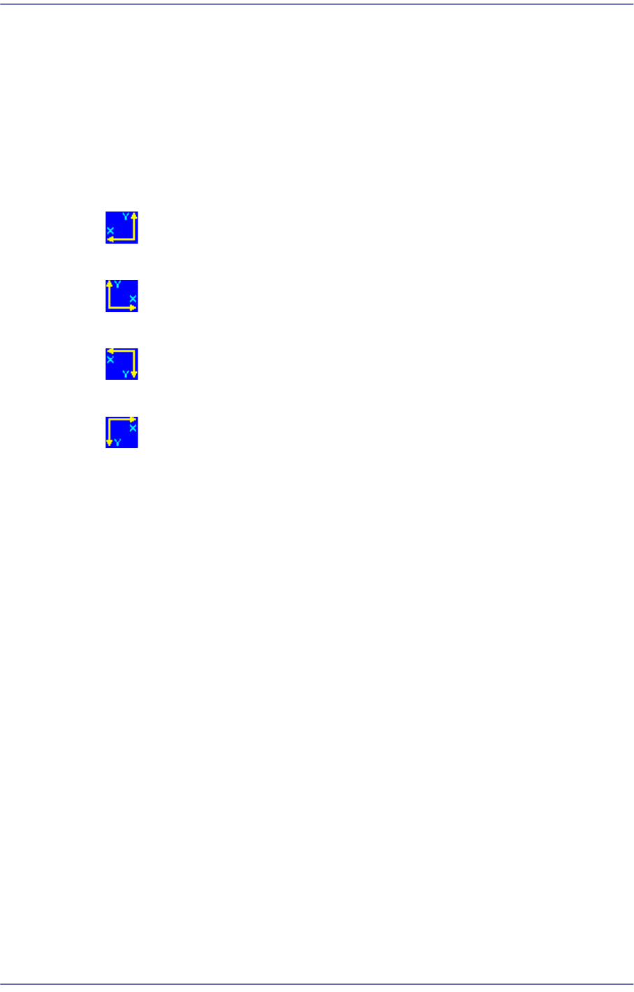
<3. Coordinate> combo box
Select the PCB coordinate system. Available coordinate systems are as follows.
Left-Up: When the PCB flows from left to right based on the front side of the
machine.
Right-Up: When the PCB flows from right to left based on the front side of the
machine.
Left-Down: When the PCB flows from left to right based on the front side of the
machine.
Right-Down: When the PCB flows from right to left based on the rear side of
the machine.
<4. Initial Theta>
Since it cannot be assumed that the PCB fed into the working area is completely
horizontal to the fixed frame of the conveyor, the user must set the initial angle (the
offset angle between the PCB and fixed frame) when making a PCB program.
If the PCB program was created with the PCB of the initially created PCB program
distorted by 1 degree, all the PCBs produced after this are worked on without
modifying the 1 degree distortion.
Therefore, teach two points at the same horizontal or vertical line on the PCB to
calculate the initial offset angle between the PCB and the fixed frame and create all
coordinates for placement.
Used to obtain CAD information on PCB fiducial by feeding the PCB into the
machine and teaching the PCB fiducial accurately when CAD data is unavailable.
Since this value is used no longer after the CAD data on the PCB fiducial is obtained,
it is initialized to ‘0’ at the time that the corresponding PCB is transferred out. Once
compensated, the offset angle is reflected automatically. Therefore, it is not needed to
compensate the offset each time.
6-3
Board Definition
Memo When performing compensation, the following conditions must be
satisfied simultaneously;
The PCB shall be transferred to the workstation of the conveyor.
The user mode shall not be ‘operator’.
More than two fiducial marks shall be set on the PCB.
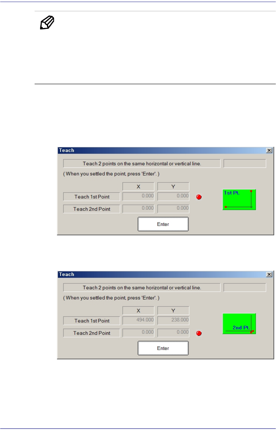
<Initial Theta - Teach> button
This Button is used to teach the initial theta of PCB. When this Button is clicked
on, the following screens are displayed in succession.
Teaching two points, which are in parallel horizontally or vertically on the PCB,
will calculate the initial angle of the PCB to compensate the PCB offset angle.
Teach the first point of the two points on the same horizontal line or vertical line
on the PCB. When the “Enter” key is pressed after teaching, the following screen
is displayed.
Teach the second point of two points on the same horizontal or vertical line on the
PCB. When the “Enter” key is pressed after teaching, the following screen is
displayed.