Hanwha SM481 PLUS Series Administrator’s Guide Eng.pdf.pdf - 第31页
Preface xvii Warning If power supply is cut off suddenly, it could result in the damage of data and machine. And the machine might be damag ed due to abnormal operation when power is supplied again.Before turning off pow…
Fast Flexible Placer SM481(L) PLUS Administrator’s Guide
xvi
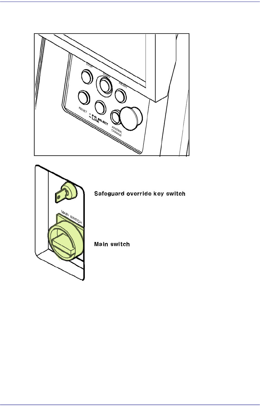
Switching of Operation Panel
Figurei.5 Operation Panel
Switching operation on the operation panel is described below.
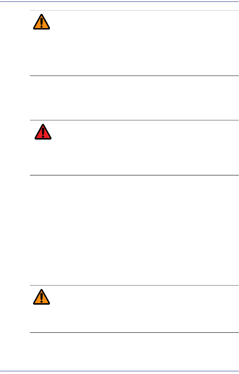
Main switch
Has a function of supplying or stopping the main power to the machine. Power is
supplied to a controller by turning the switch. A power lamp is lighted and a working
screen is shown on the programming monitor after a short delay. During the initial
stage, power is not turned on for the drivers such as motor. The power should be
turned off only after terminating the MMI. If the power is suddenly turned off, the data
and the main body may be damaged and the machine malfunction may occur at the
next power up.
Preface
xvii
Warning If power supply is cut off suddenly, it could result in the
damage of data and machine.
And the machine might be damaged due to abnormal
operation when power is supplied again.Before turning off
power, be sure to end the MMI, turn off the main switch,
then turn on the main switch after 5-10 seconds.
Safeguard override key switch
This is a key switch that can be operated artificially to prevent the door switch from
operating. It should be used limitedly only when performing initial setting or
maintenance of the machine.
Danger The Safeguard override key switch must be used by the
designated responsible personnel. It must be carefully used
for machine operation. Failure to do so may result in death
or serious personal injury if the operator approached the
drive with the safety cover Open.
Operation Panel (OP Panel)
Consists of Buttons for machine operation and the emergency stop switch.
STOP Button (Red Color)
This is a Button for temporary stopping of the operation. Automatic operation of
this machine is temporarily stopped if this Button is pressed. If this Button is
pressed while the placement is in progress, the operation is stopped after the
present operation is completed. This Button can also be used for turning off alarm
sound due to an error.
START Button (Green Color)
This is a switch for initiating the operation of this machine. Automatic operation is
initiated if this switch is pressed.
Warning Pressing the START Button without checking the presence
of worker nearby could cause injury.Be sure to check if
there is any worker near the machine before pressing the
START Button.
READY Button
This is a switch for initiating the operation of this machine. The power is supplied

Fast Flexible Placer SM481(L) PLUS Administrator’s Guide
xviii
to the driving systems such as motor. It is used to put the machine into the standby
status after power-up. ‘EMG (emergency stop)’ switch can be pressed to release
the standby state.
RESET Button (Blue Color)
Used to stop production in a machine that has paused automatic production or to
release the error in a machine that has been paused due to an error. Pressing this
Button in a machine to which an error has occurred will change the state of the
machine from 'FREEZE' or 'EMER' to 'IDLE'. The ‘Reset’ Button cannot be
activated during automatic operation of this machine.
F/R SELECTS Button
It is the Button that determines which one of the front operation panel and rear
operation panel will have the control authority. Whether or not the corresponding
operation panel has the control authority depends on the status of this Button.
When initializing the machine, the front is set to have right for control by default.
(Front side by default.)
If the select Button is pressed and maintained for a second, the LED Button is
turned on and the right for control is transferred to the rear side. It takes 0.3~1
seconds to change the right for control from the front OP panel to the rear OP
panel. The same applies when changing the right for control reversely.
The same applies for the rear side. The following table shows this briefly.
Feeder change Button
The Button used to replace the feeders on the front and rear feeder base. When this
Button is pressed, the head unit of the machine come to the safety zone for easy
feeder change.
EMG (Emergency Stop) Switch
This is an emergency stop switch. Operation of this machine is immediately
suspended if this switch is pressed in case of an emergency.
Supply of all powers except for the power to a computer is ceased. The emergency
stop status can be released by turning the ‘EMG’ switch in the direction of the
arrow and pressing the RESET Button.
Right for control
Front panel select
Button LED status
Rear panel select
Button LED status
Front On Off
Rear On Off