Hanwha SM481 PLUS Series Administrator’s Guide Eng.pdf.pdf - 第118页
6-8 Fast Flexible Placer SM481(L) PLUS Administ r ator’s Guide Edge Fixer: A method of arrangement by pushing the PCB from the side with a device attached on t he conveyor . Edge Fixer2: It is t he same as the “Ed g e Fi…
6-7
Board Definition
Set the width of PCB size.
<Conv.Width > button
Adjust the conveyor width according to the set width of the PCB.
Memo The sizes of PCB applicable for this machine are as follows.
Max.
510L×460W×4.2H [ mm ] - Single Lane/ Long Conveyor
460L×250W×4.2H [ mm ] – Dual Lane
Min.
50L×40W×0.38H [mm]
<8. Handling> group
Set the data necessary for PCB operation.
<Move Z>
After the part is picked up, set the head moving height with the surface of the PCB
being “0” when moving the head.
The default value is 4mm. However, if the placed part height is higher than 4mm,
input the height part in mm unit when it is placed on the PCB.
The height cannot be set to a value less than 4 mm. The height can be inputted up
to 12 mm. As this value becomes greater, the working time becomes longer.
Therefore, set the height to optimum value.
Caution Move Z is installation height, the test PCB shall not hang
down.
If teaching is done without checking whether a nozzle is
mounted on the Head,
the minimum movement height of head becomes low and
the head and the transport rail might collide.
Since the Z axis moving height is different for each
machine, the same value cannot be set for all machines.
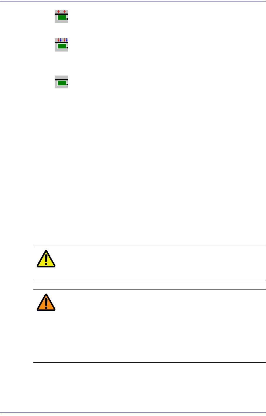
<Fix Type> combo box
Select the method for fixing a PCB.
Default: A method of fixing the PCB by moving up backup table.
6-8
Fast Flexible Placer SM481(L) PLUS Administrator’s Guide
Edge Fixer: A method of arrangement by pushing the PCB from the side
with a device attached on the conveyor.
Edge Fixer2: It is the same as the “Edge Fixer” method, but it is a method of
pushing twice from the side. If the PCB weight is greater than 1kg, select the
‘Edge Fixer2’
None: It uses only the PCB clamping method for fixing a PCB.
<PCB In> button
Loads the PCB in the operation area.
<PCB Out> button
Out the PCB in the operation area.
<PCB Unlock> button
Release the PCB fixed in the operation area.
<Stopper U/D> button
Moves up or down the work stopper, the stopper of PCB in the operation area.
<BUT U/D> button
Moves up or down the BUT (Back Up Table) that locks up the PCB in the operation
area.
<Cancel> button
Cancels the edited data.
Caution If you move to another screen while editing the “Board”
dialog box, the edited data is saved automatically.
Warning During teaching, the operator or people near the operator
could be injured due to operation error or insufficient
checking of surroundings
Before start teaching, check the device to teach one more
time, and check whether there is any worker near the
machine
6-9
Board Definition
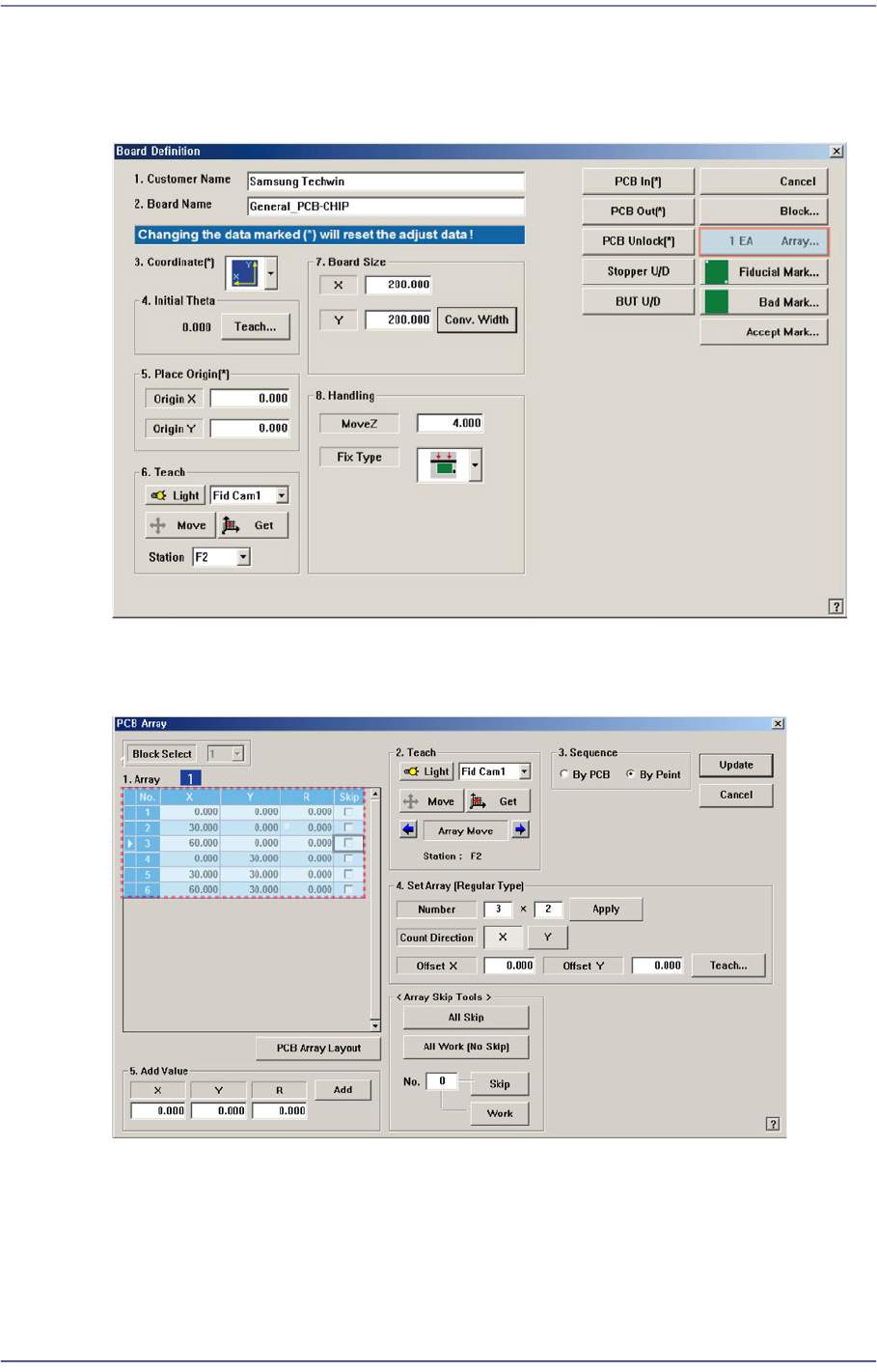
6.2. Array PCB Setup
For an array PCB, setup the offset value between the origin of the small PCB in the array
PCB and place origin of the array PCB.
When this <Array…> button is clicked on, the following dialog box is displayed.
Figure6.3 “PCB Array” dialog box
1: Grid Cell
<Block Select> combo box
For a Multi PCB
The model selected from the “Board Definition” dialog box is selected