IPC-TM-650 EN 2022 试验方法.pdf - 第107页
IPC-2-2-21-5 Figure 5 Planarity Chart for Method.xls 6.4 3.2 1.6 0.8 0.4 0.2 0.1 0.0 10.0 20.0 30.0 40.0 50.0 60.0 70.0 80.0 90.0 100.0 T race Width (mm) Planarity T est Method - Sample A Pr ofilometer Method A % Planari…
5.1.3 To
standardize measurements, use test structures in
whichb=18µm,c=63.5 µm, and the ratio of c/b is 3.5 ±
0.2. If a dielectric film is used, which has been produced at a
fixed thickness other than that outlined above, maintain a c/b
ratio as described. If the standard construction with this
defined ratio cannot be maintained, the actual metal and
dielectric thickness must be reported.
5.1.4 Make
triplicate measurements and average the results
at each line width.
5.2
Calculation of Planarity
5.2.1
Planarity
for an individual trace, P
a
,
can be defined by
the following equation:
P
a
=
(1 - d/b)100
where ‘‘a’’ is the trace width, ‘‘d’’ is the bump height over the
trace, and ‘‘b’’ is the copper trace height. For an ideal planar
structure, the value of P is equal to 100%.
5.2.2
Average
planarity, P
ave
,
for a given trace width is cal-
culated using the triplicate measurements:
P
ave
=(P
a1
+P
a2
+P
a3
)/3
5.2.3
Total average planarity, P
total
, is the average planarity
for all widths of traces (where n = number of traces widths
measured):
P
total
=(
P
ave1
+P
ave2
+
.......+ P
ave
n
)/n
5.3
Report
5.3.1
Report
the average planarity for each trace width
measured (see 5.2.2).
5.3.2
Report
the total average planarity as a single average
percentage of all seven trace width averages (see 5.2.3).
5.3.3
Also
report the technique, profilometer or cross-
section, used to obtain the measurements.
This calculation can be performed for each trace width to
develop a planarity plot.
6 Notes
6.1
Cross Section Method
Due
to the field of view
required for the larger trace widths (> 0.8 mm), accurate mea-
surements of the dielectric ‘‘bump’’ may not be possible due
to the low magnification. One option is to use a higher mag-
nification and measure the total dielectric and copper trace
height from the substrate surface and subtract the minimum
dielectric height over the substrate alone.
6.1
Planarity Test Method Sample
An
example of a pla-
narity test method is given in Figure 5.
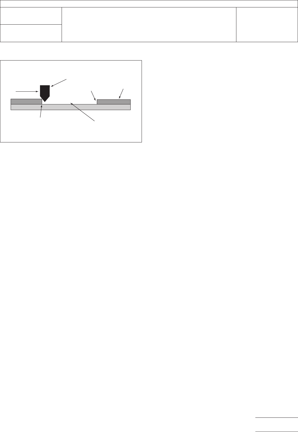
IPC-2-2-21-4
Figure
4 Cross Section of Window Used for Dielectric
Thickness Measurement
Pr
ofilometer Stylus
Direction
of Scan
Height at Exit
Dielectric
Height at Entry
``Window´´ in Dielectric
IPC-TM-650
Number
2.2.21
Subject
Planarity
of Dielectrics for High Density Interconnection (HDI)/
Microvia Technology
Date
11/98
Revision
P
age3of4
电子技术应用 www.ChinaAET.com
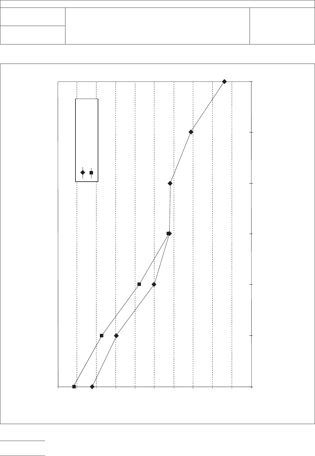
IPC-2-2-21-5
Figure
5 Planarity Chart for Method.xls
6.4
3.2
1.60.8
0.40.2
0.1
0.0
10.0
20.0
30.0
40.0
50.0
60.0
70.0
80.0
90.0
100.0
T
race Width (mm)
Planarity Test Method - Sample A
Pr
ofilometer Method A
% Planarity
X-Section Method A
IPC-TM-650
Number
2.2.21
Subject
Planarity
of Dielectrics for High Density Interconnection (HDI)/
Microvia Technology
Date
11/98
Revision
P
age4of4
电子技术应用 www.ChinaAET.com

1 Purpose This procedure establishes proper methods and
practices for quantifying the surface topography/texture of
metallic foil using a noncontact, optical or laser, 3-D surface
measurement device. The primary reported values will include
Sa, Sq and Sz (see 6.3 for further information on these param-
eters) where S values are 3-D measures.
2 Applicable Documents
2.1 IPC
1
IPC-4562 Metal Foil for Printed Board Applications
2.2 International Standards
2
ISO 16610 Geometrical Product Specifications (GPS) –
Filtration
ISO 25178-2 Surface Texture: Areal – Part 2: Terms, Defini-
tions and Surface Texture Parameters
3 Metallic Foil Sample Preparation
3.1
The samples tested will be a single-layer material taken
from a representative location of metallic foil. The size of the
physical sample will be determined based on the easiest
method for obtaining a representative sample, but should be
no larger than 50 mm x 50 mm [nominally 2 in x 2 in]. Opera-
tors of the measurement tool will orient the sample so the
measurements are across the machine direction of the foil
sample or the surface of the Physical NIST Traceable
Standards.
3.2 The samples will be tested as received, but proper care
must be taken to prevent scratches, dents or bending to
insure the integrity of the surface. Operators of the measure-
ment tool will orient the sample so that the measurements are
across the machine direction of the foil sample.
4 Equipment / Environment
4.1
A noncontact 3-D tool will be used for this procedure
and it will be calibrated according to the machine manufactur-
er’s instructions.
Examples: Wyko-NT-1100, Zygo 5000, Zygo 600, Veeco
NT-9300, Keyence VK-9700 or equivalent.
4.2 The tool will be placed on a lab bench or other sturdy
table top and should be placed in an area away from
machines that produce large amounts of noise/vibration.
Follow test device manufacturer’s recommendations for envi-
ronmental conditions, including for vibration.
5 Procedure for testing upon metallic foil and physical
NIST Traceable Standards
5.1
The operator will set up the measurement tool program
to scan a minimum area of 200,000 square microns having a
maximum length to width aspect ratio of 5:1 with an objective
magnification of 50X for measuring the surface roughness of
either a physical standard or a foil sample. Such specification
requirements may necessitate stitching or ‘‘step and repeat-
ing’’ multiple images so as to obtain data from a properly
sized area.
5.2 No filters shall be used with this test method.
5.3 Prior to measurement of metallic foil samples the tool
operator will assure the 3-D tool is currently properly cali-
brated. Verification needs to be performed by testing the
actual physical NIST Traceable Standards at least monthly on
the 3-D measurement tool.
5.4 Physical Standards will be oriented so the measurement
is perpendicular to the grain of the Standards. Operator will
locate the measurement center point in the XY axis to match
the XY center point of the specific patch being measured on
the Standard set. This is done to assure the measurement
always takes place in the same location upon the Standard
surface.
1. www.ipc.org
2. www.iso.org
3000 Lakeside Drive, Suite 105N
Bannockburn, IL 60015-1249
IPC-TM-650
TEST METHODS MANUAL
Number
2.2.22
Subject
Noncontact Metallic Foil Surface Topography/
Texture
Date
5/20
Revision
Originating Task Group
Metallic Foil Task Group (3-12a)
Material in this Test Methods Manual was voluntarily established by Technical Committees of IPC. This material is advisory only
and its use or adaptation is entirely voluntary. IPC disclaims all liability of any kind as to the use, application, or adaptation of this
material. Users are also wholly responsible for protecting themselves against all claims or liabilities for patent infringement.
Equipment referenced is for the convenience of the user and does not imply endorsement by IPC.
Page1of5