IPC-TM-650 EN 2022 试验方法.pdf - 第630页
6.1 Ground Measurement Determination of tip-to-ground resistance is accomplished by using a basic ohmmeter circuit as represented in Figure 2. It works by passing a current through the tip and its grounding circuit and m…

1
Scope
This
test method describes the measurement of
the DC tip-to-ground resistance of an electric hand soldering/
desoldering tool designed with a grounded tip. Measurement
of tip-to-ground AC reactance is outside the scope of this test
method. Also, measurement of soft grounded or equipment
with insulated tips is outside the scope of this test method.
There are three times when ground testing should be done:
• Equipment qualification for purchase
• Incoming inspection of new or repaired equipment
• Process monitoring (periodic checks)
Determination of tip-to-ground resistance is accomplished by
using a basic ohmmeter circuit, passing a current through the
tip and its grounding circuit and measuring the resultant volt-
age drop. The values used in this test eliminate error caused
by the Seebeck (thermocouple) effect.
Warning
This
is a laboratory test procedure that may, of
necessity, expose terminals that carry line voltages. All stan-
dard laboratory safety procedures regarding the setup and
performance of tests with line voltage equipment must be
observed at all times.
Caution
This
test is performed with soldering systems at
their normal operating temperature. Test personnel must take
adequate precautionary steps to protect themselves and oth-
ers from potential burns.
2
Applicable Documents.
ANSI/J-STD-001
Requirements
for Soldered Electrical and
Electronic Assemblies.
IPC-TM-650
Test
Methods Manual
2.5.33 Measurement of Electrical Overstress from Solder-
ing Hand Tools
3
Test Specimens
Test
specimens for this procedure are
detailed in Method 2.5.33.
4
Equipment/Apparatus
4.1
Test
electrode per Method 2.5.33
4.2
Constant
current source capable of providing 10 milli-
amps DC
4.3
DC
millivoltmeter capable of measuring at least 60 mv
DC and having a resolution of 1 mv DC
4.4
Resistor,
4.99Ω 1% precision
1
⁄
4
w
or greater (any com-
mercially available brand carbon or metal film)
4.5
Preparation of Apparatus
Connect
the apparatus as
illustrated in Figure 1. The negative electrode of the test appa-
ratus shall make a good electrical connection to the ground
reference point of the Unit Under Test (UUT). The UUT shall be
turned on and adjusted (if applicable) to achieve normal oper-
ating temperature.
Note: The plug is in the receptacle during measurements.
It’s shown unplugged in Figure 1 for clarity. Non-US power
receptacles may be different from that illustrated.
4.6 Calibration and Standardization
The
apparatus is
checked by separately placing two resistive elements across
the test apparatus’s electrodes: a shorting wire (0.0Ω) and
4.99Ω 1% precision
1
⁄
4
w
or greater resistor. The combination
of the current source and the measuring/indicating device will
be accurate to within ± 0.2Ω (± 4% of upper limit).
5
Procedure
Once
the electrodes are in position and the
test apparatus is operating, touch the HOT tip of the UUT to
the tinned area of the test electrode. Apply solder to form a
good electrical contact. Wait for the reading to stabilize, then
record the reading.
5.1
Calculation and Interpretation of Results
Even
though
the meter reads out millivolts, using 10 ma DC for
excitation current results in the displayed numbers represent-
ing the resistance in ohms without calculation, except for
decimal place shifting (i.e., a readout of 30 mv dc indicates
3.0Ω).
The reading shall be equal to or less than 5.0Ω.
6 Notes
If
tracking test results, record the measured values
on a copy of the form found in Method 2.5.33.
The
Institute for Interconnecting and Packaging Electronic Circuits
2215 Sanders Road • Northbrook, IL 60062
IPC-TM-650
TEST
METHODS MANUAL
Number
2.5.33.1
Subject
Measurement
of Electrical Overstress from
Soldering Hand Tools - Ground Measurements
Date
11/98
Revision
Originating Task Group
Manual Soldering Task Group (5-22c)
Material
in this Test Methods Manual was voluntarily established by Technical Committees of the IPC. This material is advisory only
and its use or adaptation is entirely voluntary. IPC disclaims all liability of any kind as to the use, application, or adaptation of this
material. Users are also wholly responsible for protecting themselves against all claims or liabilities for patent infringement.
Equipment referenced is for the convenience of the user and does not imply endorsement by the IPC.
P
age1of3
电子技术应用 www.ChinaAET.com
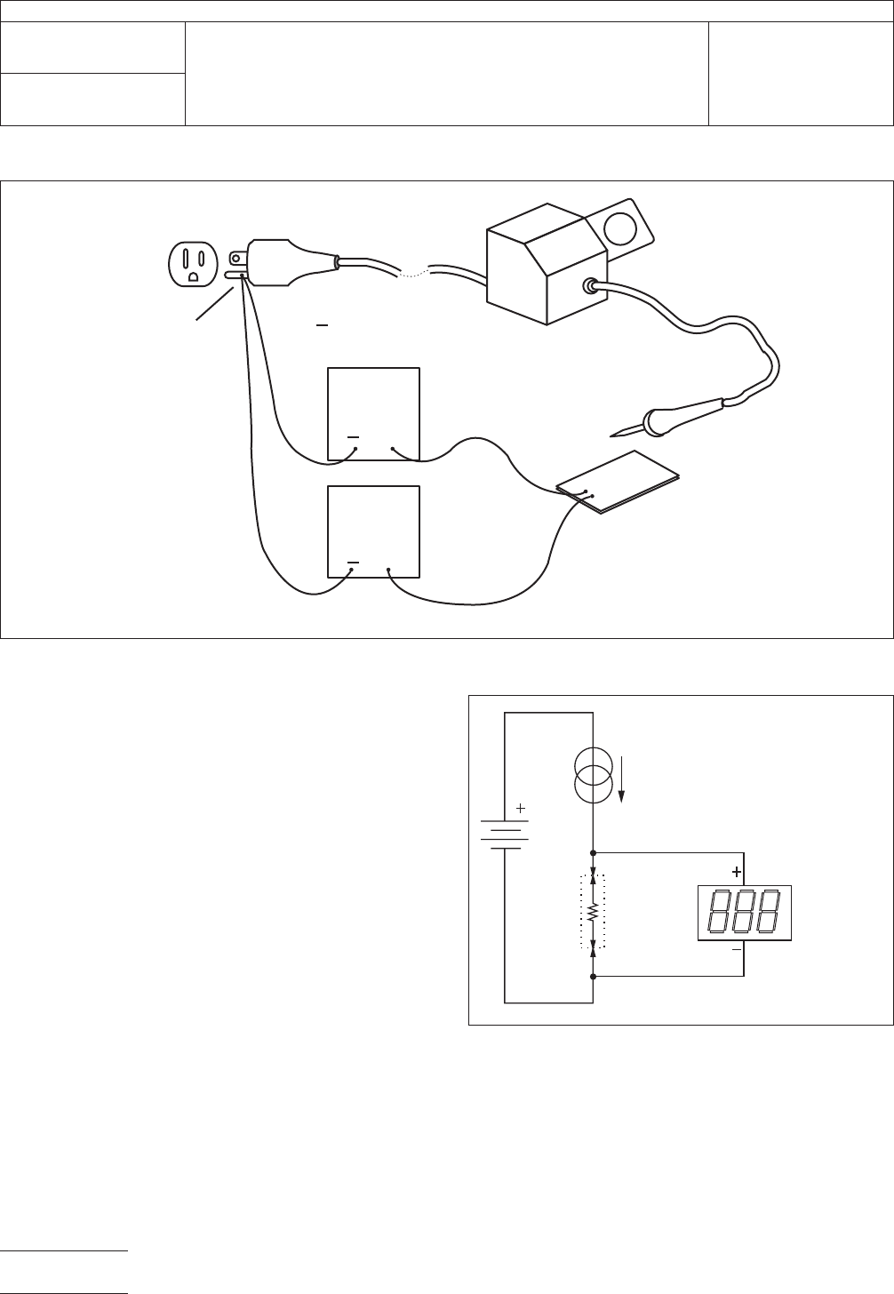
6.1
Ground Measurement
Determination
of tip-to-ground
resistance is accomplished by using a basic ohmmeter circuit
as represented in Figure 2. It works by passing a current
through the tip and its grounding circuit and measuring the
resultant voltage drop. This test method recognizes the ther-
mocouple effect present due to the assembly comprising dif-
ferent metallic materials whose junctions operate at different
temperatures (including the test apparatus electrodes). Test-
ing using ohmmeters having too low excitation current has
resulted in the thermocouple voltage introducing a significant
error or even causing a negative resistance reading. Error from
the thermocouple effect is made insignificant by increasing the
excitation current, thus increasing the voltage drop. Testing
has demonstrated an excitation current of 10 milliamps suf-
fices.
The voltage measuring device must indicate the voltage drop
in such a manner that the reading the operator sees directly
reflects the resistance in ohms and tenths of ohms. No calcu-
lations other than decimal place shifting should be used.
6.2
Constant Current Source
The
constant current
source can be an off-the-shelf unit, a custom-built active cir-
cuit, or a simple passive circuit. Figure 3 shows a very simple
way to achieve a 10 ma source accurate enough for measur-
ing soldering systes.
This circuit works because the battery voltage is high com-
pared to the drop across the UUT. Assume a battery voltage
of 48 volts and a dropping resistor of 4800 ohms. When the
resistance of the UUT equals zero, the current will be 10 ma.
IPC-2.5.33.1-1
Figure
1 Test Apparatus
10 MA.
CURRENT
SOURCE
GROUND
REFERENCE
POINT
MILLI-
VOL
T
METER
+
+
+
ELECTRODE
( )
UNIT
UNDER
TEST (UUT)
TEST
ELECTRODE ( )
IPC-2.5.33.1-2
Figure
2 Block Diagram of Test Apparatus
UUT
10 MA
CURRENT
REGULA
TOR
MILLIVOLT
METER
IPC-TM-650
Number
2.5.33.1
Subject
Measurement
of Electrical Overstress from Soldering Hand
Tools - Ground Measurements
Date
11/98
Revision
P
age2of3
电子技术应用 www.ChinaAET.com
If
the resistance of the UUT rises to the upper limit of 5Ω, the
current will be 9.989 ma, just outside 0.1% on the low side.
This inaccuracy is well within the limits of the stanard.
T
able 1 Examples for Battery, Dropping
Resistor, and Accuracy
V
R Accuracy
6
600 -0.8%
9 900 -0.6%
12 1200 -0.4%
24 2400 -0.2%
48 4800 -0.1%
IPC-2.5.33.1-3
Figure
3 Simple Constant Current Source
UUT
0
TO 5
OHMS
10 MA
CURRENT
R
V
MILLIVOLT
METER
IPC-TM-650
Number
2.5.33.1
Subject
Measurement
of Electrical Overstress from Soldering Hand
Tools - Ground Measurements
Date
11/98
Revision
P
age3of3
电子技术应用 www.ChinaAET.com