IPC-TM-650 EN 2022 试验方法.pdf - 第333页
5.3.2 Determination of Cure Factor (Delta T g ) Cure Fac- tor (or Delta T g ) is the absolute difference between the glass transition temperatures determined in the two scans, where: Cure Factor (Delta T g )=T g2 -T g1 T…
5.2.2.2 Perform the pre-scan from at least 30 °C [54 °F]
below the transition region to a temperature 10 °C [18 °F]
above the transition region at a rate of 20 °C/min [36 °F/min].
Then quench-cool to at least 30 °C [54 °F] below the transi-
tion region, as rapidly as possible.
5.2.3 Analysis Scan.
5.2.3.1 Start the scan at a temperature that is at least 30 °C
[54 °F] lower than the anticipated transition region. The heat
rate shall be stabilized before the transition region is reached.
5.2.3.2 Unless otherwise specified, scan at a rate of 20 °C/
min [36 °F/min].
5.2.3.3 When the transition has been observed, scan at
least 30 °C [54 °F] beyond the transition region.
5.2.3.4 Record the results as T
g1
.
5.2.4 Determination of Cure Factor.
5.2.4.1 The following steps shall be performed only if the
Cure Factor is applicable and required by the governing speci-
fication (see Table 1). It does not apply to prepreg.
5.2.4.2 Continue the scan at a rate of 20 °C/min [36 °F/min]
to a temperature per Table 1. The specimen is then held at
the isothermal temperature for a time per Table 1.
5.2.4.3 The specimen is immediately cooled to initial condi-
tions and a second glass transition scan carried out in accor-
dance with 5.3.3. Record as T
g2
.
5.3 Calculation
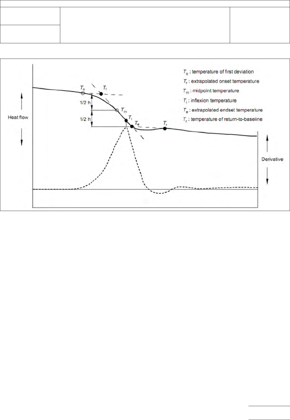
5.3.1 Determination of T
g
The midpoint temperature T
m
(°C) as described in Figure 1 reported as the T
g
.T
g
is the point
on the thermal curve corresponding to 1/2 the heat flow dif-
ference between the extrapolated onset and extrapolated
end. If suitable computer software is available, the automatic
calculation of the glass transition temperature is allowable pro-
vided the value calculation is either the midpoint or the steep-
est deflection and not the onset temperature. See Figure 1.
Table 1 Resin Type Temperature Requirements
Resin Type Isothermal
1
Temperature Hold Time at Temperature
Difunctional and Tetrafunctional Epoxies 175 °C±2°C 15±0.5minutes
Multifunctional and High Temperature Epoxies 190 °C±5°C 15±0.5minutes
BT- Epoxies
2
N/A N/A
Polyimides
2
N/A N/A
Cyanate Esters
2
N/A N/A
1) Or in accordance with manufacturer’s recommendations.
2) Certain materials are not compatible with the Cure Factor determination, as they will exhibit an increasing transition temperature
with each exposure to a temperature above the cure level.
IPC-TM-650
Number
2.4.25
Subject
Glass Transition Temperature and Cure Factor by DSC
Date
11/17
Revision
D
Page2of4
5.3.2 Determination of Cure Factor (Delta T
g
) Cure Fac-
tor (or Delta T
g
) is the absolute difference between the glass
transition temperatures determined in the two scans, where:
Cure Factor (Delta T
g
)=T
g2
-T
g1
T
g1
=T
g
of first scan
T
g2
=T
g
of second scan
5.4 Report
5.4.1
The glass transition temperature (delta T
g
) shall be
reported for each specimen.
5.4.2 The Cure Factor shall be reported, if applicable, and
specified for each specimen.
5.4.3 The scan rate, specimen preparation, isothermal tem-
perature, hold time, and method of midpoint determination
shall be reported if other than that specified in this method.
5.4.4 The specimen size, configuration, and preparation
shall be reported.
6 Notes
6.1 Powdered Specimens
Certain materials may be more
appropriately tested using a specimen that is a powder pre-
pared by grinding or filing the sample. Consult with the equip-
ment’s instructions and with the material manufacturer for
more information.
6.2 Calibration of the instrument shall be carried out
according to the manufacturer’s instructions with at least
one standard being indium.
6.2.1 Computer Determination of T
g
If suitable computer
software is available, the automatic calculation of the glass
transition temperature is allowable, provided the value calcu-
lated is either the midpoint or the point of steepest deflection.
and not the onset temperature.
Calibration of the instrument must be carried out according to
the manufacturer’s instructions, with at least one standard
being indium.
Figure 1 Typical DSC Plot
IPC-TM-650
Number
2.4.25
Subject
Glass Transition Temperature and Cure Factor by DSC
Date
11/17
Revision
D
Page3of4

6.3 The glass transition for a given material will be signifi-
cantly different if measured by DSC versus TMA. The test
equipment used should be noted beside the glass transition
valve, i.e., 136.4 °C (DSC) or 132.6 °C (TMA).
6.4 Cure Factor is also described as Delta T
g
.
6.5 Testing of single-sided or unclad laminates manufac-
tured without metallic cladding on either side.
6.5.1 Single-sided or unclad laminates exhibit unreliable
Cure Factor data, due to effects of moisture and other factors.
It is recommended that Cure Factor requirements not be
applied to these laminate configurations.
6.5.2 Single-sided or unclad laminates typically exhibit T
g
approximately 8 °C to 15 °C lower than equivalent laminates
that are clad on both sides. Accordingly, the specification
requirements should take this into consideration. Reasons for
the T
g
‘‘loss’’ include presence of moisture in the release films
used in place of metallic cladding.
IPC-TM-650
Number
2.4.25
Subject
Glass Transition Temperature and Cure Factor by DSC
Date
11/17
Revision
D
Page4of4