IPC-TM-650 EN 2022 试验方法.pdf - 第230页
5.3.4 The flexural fatigue life at bend radii other than man- drel radius can also be obtained by evaluating the ductility for- mula for the flex life in cycles-to-failure using the fatigue duc- tility determined in 5.3.…
Note:
For
flexural fatigue tests lasting in excess of 1000
cycles, the adhesive tape attachment needs to be substantial
enough to prevent relative sliding of specimen and sample
holder as a result of the cyclic flexure movements.
5.2
Test Procedure
5.2.1
Mount
mandrels to flex tester, adjust the support
roller positions for a clearance of 1.27 mm [0.05 inch] (shim
provided) between rollers and mandrels.
Note:
For
the ductility test, it is important that the specimens
fail between 30 and 500 cycles. Mandrels with 2.0 or 1.0 mm
[0.079 or 0.040 inch] diameter are suggested but for some
samples, mandrel diameters different from these diameters
might be necessary. Larger mandrel diameters result in longer
cyclic life and smaller diameters in shorter life.
5.2.2
Mount
test specimen between mandrels, attach relay
leads with alligator clips to foil weight wing nut to form ‘‘slip-
off’’ electrical connections, plug relay leads into relay jacks,
set counter to zero, and start flex tester.
5.2.3 Complete
separation of the foil specimen constitutes
failure and the flex tester stops automatically when the drop-
ping foil weight dislodges the alligator clips from the wing nut.
5.2.4
Record
cycles-to-failure indicated on counter.
5.3
Evaluation
5.3.1 Ductility Test
5.3.1.1
Calculate
the ductility for each specimen by itera-
tively solving the formula below:
N
f
−0.6
D
f
0.75
+ 0.9
S
u
E
[
exp(D
f
)
0.36
]
(0.1785
log
10
5
N
f
)
−
2t
M
21+t
= 0
where:
D
f
=
fatigue ductility, inch/inch (x100,%)
N
f
=
cycles-to-failure
S
u
=
ultimate tensile strength, psi
E = modulus of elasticity, psi
t
M
=
core thickness, inch
t = specimen micrometer thickness, inch
1 = mandrel radius of curvature, inch within 0.005 mm
[0.0002 inch]
Note:
Determine
S
U
as
per Test Method 2.4.18 of IPC-TM-
650. Determine E during the test for S
U
by
unloading and
reloading after about 2% elongation and measuring the slope
of the reloading curve.
Note:
The
determination of E foils is not a straightforward
procedure. It is therefore suggested that for specification pur-
poses standard values of E be adopted. For copper foil such
standard values might be: E(CF−E)=12x10
6
psi
for electro-
deposited foil, E(CF−W)=16x10
6
psi
for wrought (rolled) foil.
Note:
The
calculator program described in paragraph 6.2
solves the ductility formula and conveniently prompts for all
necessary input parameters.
5.3.1.2
Report
the average ductility from at least three
specimens.
5.3.2
Fatigue Test
The
number of cycles to failure, is the
flexural fatigue life in fully reversed bending for the bend radius
corresponding to the radius (1/2 diameter) of the test man-
drels used. An average flexural life from at least three speci-
mens should be reported.
5.3.3
Fatigue Behavior
The
fatigue behavior of a sample
can be obtained by determining the flexural fatigue life with a
number of different-diameter mandrels. Plotting the results in
a strain range versus fatigue life Manon-Coffin plot log ∆ε =
[2t
M
/(21 +
t)] versus log N
f
)
allows intra- and extrapolation to
other bend radii or fatigue lives.
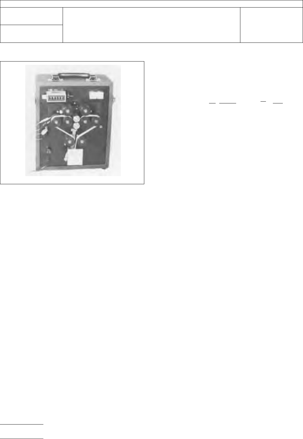
IPC-2421-2
Figure
2 Fatigue ductility flex tester
IPC-TM-650
Number
2.4.2.1
Subject
Flexural
Fatigue and Ductility, Foil
Date
3/91
Revision
D
P
age2of3
电子技术应用 www.ChinaAET.com

5.3.4
The
flexural fatigue life at bend radii other than man-
drel radius can also be obtained by evaluating the ductility for-
mula for the flex life in cycles-to-failure using the fatigue duc-
tility determined in 5.3.1.2 and the desired bend radius.
6.0 Notes
For
further technical details, reference the mate-
rial shown below.
6.1 Document
in paragraph 2.0 (IPC-TP-204).
6.2 Engelmaier,
W., ‘‘Fatigue Ductility for Foils and Flexible
Printed Wiring,’’ Program No. 1883D HP-67/97 User’s
Library, Hewlett Packard Co., Corvallis, Oregon, 1978.
6.3
Engelmaier,
W., ‘‘Fatigue Ductility Flex Tester,’’ Drawing
L520163, Bell Telephone Laboratories, Inc., Whippany, New
Jersey, 1978.
6.4
Test Equipment Sources
The
equipment sources
described below represent those currently known to the
industry. Users of this test method are urged to submit addi-
tional source names as they become available, so that this list
can be kept as current as possible.
6.4.1
Fatigue
Ductility Flex Tester, Universal Tool & Machine
Inc., 171 Coit St., Irvington, NJ 07111; 201-374-4400.
6.4.2
JDC
Precision Sample Cutter, Model JDC 125-N or
equal.
IPC-TM-650
Number
2.4.2.1
Subject
Flexural
Fatigue and Ductility, Foil
Date
3/91
Revision
D
P
age3of3
电子技术应用 www.ChinaAET.com

1.0
Scope
With
this test method the flexural fatigue life for
any given bend radius, the flexural fatigue behavior and the
ductility in percent deformation after tensile failure can be
determined.
Note:
The
indirect determination of foil ductility by using a
fatigue test is made necessary by the geometry and dimen-
sions of foil samples which make tensile elongation and rup-
ture tests inadequate for ductility determination.
2.0
Applicable Documents
IPC-TM-650
Method
2.1.1, Microsectioning
Method 2.4.18, Tensile Strength and Elongation, Copper Foils
3.0
Test Specimen
Foil
of sufficient size to permit cutting
of three 3.2 mm [1/8 inch] wide specimens of at least 50.8
mm [2 inches] in length. Specimens must be clean cut and
free of burrs and nicks.
4.0
Apparatus
4.1
Ductility
Flex Tester, Universal Mfg., Model FDF or 2FDF
or equal (see 6.4 and Figure 2).
4.2
Sample
cutter, punch or tensile cut router. Note 6.4.
4.3
Micrometer
tool capable of measurement to the nearest
0.0025 mm [0.0001 inch].
4.4
Programmable
Calculator, Hewlett-Packard HP-67, or
equivalent.
4.5
Sample
holders, 203.2 x 12.7 mm [8 x 1/2 inch], of very
flexible but durable material, e.g., epoxy-impregnated glass
cloth, paper, etc.
4.6
Microscope
5.0 Procedure
5.1 Preparation of Samples
5.1.1
The
samples should be smooth and undistorted
(wrinkle free).
5.1.2
Use
the sample cutter to cut the 3.2 mm [1/8 inch]
wide test specimen. Examine each specimen for nicks, cuts,
or curled edges. Discard any specimen with defects.
5.1.3
Use
the micrometer to determine the specimen thick-
ness, t, in center of each specimen to the nearest 0.0025 mm
[0.0001 inch]. If one or both specimen surfaces are rough, it
is necessary to determine the core thickness, t
M
from
a micro-
section (see Figure 1).
Note:
Thickness
is a critical parameter in the determination of
fatigue ductility. A 10% error in t
M
results
in a 14% error in D
f
.
Note:
The
core thickness, t
M
,
is preferably determined as a
fraction of the specimen thickness, t, from a microsection pre-
pared per IPC-TM-650, method 2.1.1 and measured with a
metallurgical microscope at 200X minimum with a suitable filar
eyepiece or reticle. The measurement is to be made from the
valley of the rough surface to the smooth surface, or valley to
valley, where both surfaces are rough. The t
M
is
to be made
once on a batch or lot basis, and this fractional value of t
M
/t
is
then multiplied by all other micrometer, t, values to achieve
core values for all samples.
Note:
Care
must be taken that during thickness measure-
ments the specimens are not compressed or surface rough-
ness crushed, producing false low thickness readings.
5.1.4
Attach
test specimen to the ends of 2 sample holders
with adhesive tape and clamp 84 grams [3 ounce] foil weight
(not the 8 ounce weight shown in Figure 2) to the free ends of
the sample holders to form a loop (See Figure 2).
IPC-2421-1
Figure
1 Smooth and rough foil
▼
▼
t
M
t
▼
▼
▼
▼
t = t
M
The
Institute for Interconnecting and Packaging Electronic Circuits
2215 Sanders Road • Northbrook, IL 60062-6135
IPC-TM-650
TEST
METHODS MANUAL
Number
2.4.2.1
Subject
Flexural
Fatigue and Ductility, Foil
Date
3/91
Revision
D
Originating Task Group
N/A
Material
in this Test Methods Manual was voluntarily established by Technical Committees of the IPC. This material is advisory only
and its use or adaptation is entirely voluntary. IPC disclaims all liability of any kind as to the use, application, or adaptation of this
material. Users are also wholly responsible for protecting themselves against all claims or liabilities for patent infringement.
Equipment referenced is for the convenience of the user and does not imply endorsement by the IPC.
P
age1of3
电子技术应用 www.ChinaAET.com