IPC-TM-650 EN 2022 试验方法.pdf - 第600页
5.3.4 All electrical measurements shall be made using 500 volts direct current. The voltage shall be applied to the speci- men for 60 +5, -0 seconds prior to taking the actual reading, for stabilization purposes. 5.3.5 M…

5.1.1.1
Metallic-clad
materials having a thickness of less
than 0.51 mm [0.020 in] shall be photoprinted with a pattern
of the outline of the conductors and etched in accordance
with IPC-TM-650, Methods 2.3.6, 2.3.7, or 2.3.7.1. The elec-
trodes shall then be completed (filled in) using silver conduc-
tive paint.
5.1.1.2
Metallic-clad
laminates 0.51 mm [0.020 in] or thicker
shall be etched in accordance with IPC-TM-650, Method
2.3.6, 2.3.7, or 2.3.7.1. A pattern of the outline of the conduc-
tors may be photoprinted before etching. Test electrodes shall
be applied using silver conductive paint and an appropriate
test pattern application system.
5.1.1.3
Solid
metal foil electrodes shall not be acceptable in
any case, except for the outer electrode for laminates less
than 0.51 mm [0.020 in]. A small pad of retained cladding may
be retained within the electrode borders to facilitate soldering
of leads.
5.1.2
If
soldering techniques are used to attach leads, suit-
able cleaning procedures shall be used to remove flux and
other residue.
5.2
Conditioning
5.2.1 Humidity Conditioning
5.2.1.1
Specimens
of a thickness less than 0.51 mm [0.020
in] shall be subjected to 90 + 5-0% relative humidity and 35 ±
2°C [95 ± 3.6°F] for a period of 96 +2, -0 hours prior to elec-
trical measurement.
5.2.1.2
Specimens
of a thickness greater than, or equal to,
0.51 mm [0.020 in] shall be subjected to the conditioning
specified in IPC-TM-650, Method 2.6.3, paragraph 5.1.3. Fol-
lowing the tenth cycle, the conditioning chamber shall main-
tain a temperature of 25 ± 2°C [77 ± 3.6°F] and 90 +5, 0%
relative humidity during the interval that electrical measure-
ments are being made.
5.2.2
At Elevated Temperature Conditioning
Speci-
mens
shall be subjected to the specified temperature (based
on material type and specification requirements) for a period
of 24 hours -0, +2 hours. Unless otherwise specified, the tem-
perature shall be 125 ± 2°C [257 ± 3.6°F].
5.3
Electrical Measurements
All
electrical measurements
shall be made inside the applicable conditioning chamber and
at the conditions specified in 5.2.
5.3.1
Electrical
measurements taken on specimens condi-
tioned in accordance with paragraph 5.2.1 shall be completed
within the 2 hour tolerance of the conditioning.
5.3.2
Electrical
measurements taken on specimens condi-
tioned in accordance with paragraph 5.2.2 shall be made after
achieving 1.5 hours steady state of 25 ± 2°C [77 ± 3.6°F] and
90 +5, -0% relative humidity. All measurements shall be com-
pleted within 2 hours.
5.3.3 Electrical
measurements taken on specimens condi-
tioned in accordance with paragraph 5.3 shall be completed
within the 2 hour tolerance of the conditioning.
Dimension
Table
Base
Thickness
D
1
Diameter
D
2
Diameter
D
3
Diameter
D
4
D
5
A(cm
2
)
P/D
4
Less
than
0.51 mm
(0.020 inches)
1.000
(2.540)
1.020
(2.591)
1.375
(3.493)
0.010
(0.025)
0.177
(0.460)
5.169 317.4
±0.005
(0.013)
±0.005
(0.013)
±0.005
(0.013)
±0.001
(0.003)
±0.005
(0.013)
0.51 mm
(0.020 inches)
and greater
2.000
(5.080)
2.500
(6.350)
3.000
(7.520)
0.250
(0.636)
0.250
(0.636)
25.652 28.27
±0.015
(0.038)
±0.015
(0.038)
±0.015
(0.038)
±0.005
(0.038)
±0.015
(0.038)
For the above: Do = (D
1
+D
2
)/2
A=πDo
2
4
P=πD
O
Note:
Dimensions
are in inches with metric equivalents in parenthesis (1 inch = 2.54 cm).
IPC-TM-650
Number
2.5.17.1
Subject
Volume
and Surface Resistivity of Dielectric Materials
Date
12/94
Revision
A
P
age2of4
电子技术应用 www.ChinaAET.com
5.3.4
All
electrical measurements shall be made using 500
volts direct current. The voltage shall be applied to the speci-
men for 60 +5, -0 seconds prior to taking the actual reading,
for stabilization purposes.
5.3.5
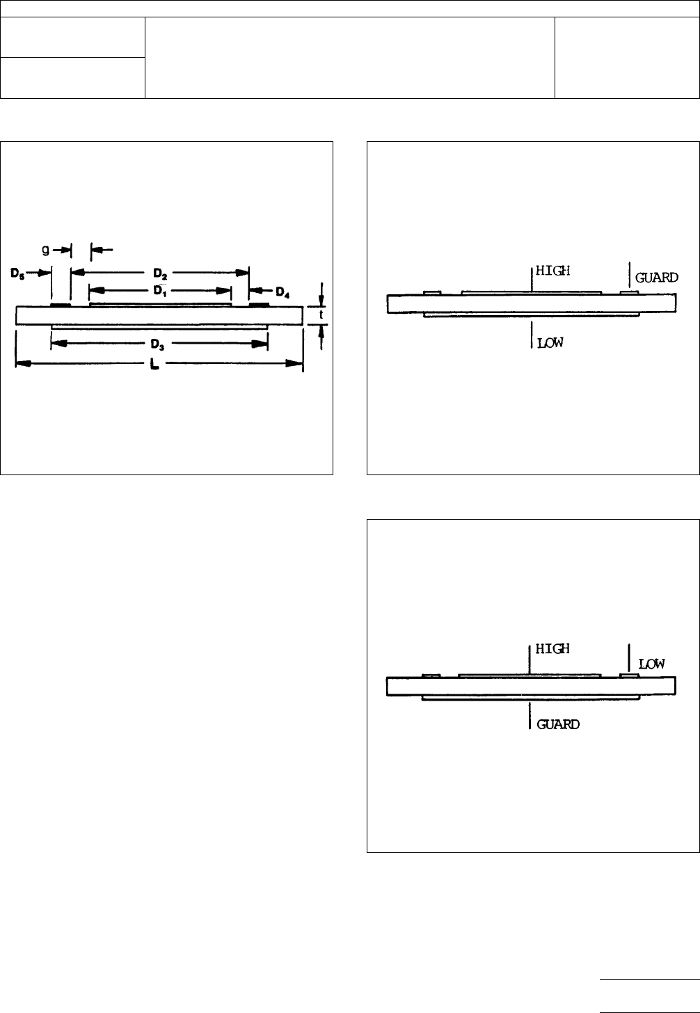
Measure
the volume resistance by connecting the
resistance measuring device to the specimen electrodes
through the fixture system as described in 4.5 in accordance
with Figure 2.
5.3.6
Measure
the surface resistance by interchanging the
test cables connecting the solid back electrode and the outer
ring to the instrument for the arrangement shown in Figure 3.
5.4
Specimen Thickness
Each
specimen shall be mea-
sured for its thickness without cladding. Specimens for each
test condition shall have their thickness readings averaged.
Figure
1 Test pattern dimensions (See table)
Figure
2
Figure
3
IPC-TM-650
Number
2.5.17.1
Subject
Volume
and Surface Resistivity of Dielectric Materials
Date
12/94
Revision
A
P
age3of4
电子技术应用 www.ChinaAET.com

5.5
Calculations
5.5.1
The
volume resistivity shall be calculated as follows:
r=RA
T
Where:
r = Volume resistivity in megohm-centimeters
R = Measured volume resistance in megohms
A = Effective area of the guarded electrode in square centi-
meters
T = Average thickness of specimen in centimeters
T = (t) x 2.54 [see 5.2.1]
t = Average thickness (t) in inches (from 5.4)
Note:
The
value of A may be obtained from the Dimension
Table.
5.5.2
The
surface resistivity shall be calculated as follows:
r
1
=R
1
P
D4
Where:
r
1
=
Surface resistivity in megohms
R
1
=
Measured surface resistance in megohms
P = Effective perimeter of the guarded electrode in centime-
ters
D4 = Width of the test gap in centimeters
Note:
The
ratio of P/D4 for the electrode configuration being
used may be obtained from the Dimension Table included in
Figure 1.
5.6
Reporting
5.6.1
The
volume resistivity of each specimen and the aver-
age shall be reported. Each condition tested shall be reported
separately.
5.6.2 The surface resistivity of each specimen and the aver-
age shall be reported. Each condition shall be reported sepa-
rately.
5.6.2.1 The
surface resistance is the direct reading of the
megohmeter scale and should be recorded in megohms.
6.0
Notes
6.1
For
additional information see ASTM-D-257, D-C Resis-
tance or Conductance of Insulating Materials.
6.2
The
system of electrical connections to the specimens
may benefit from a coaxial cable set-up designed to shield the
measurement of volume or surface resistances from electrical
interference.
6.3
Performance Specifications
The
following informa-
tion should be reviewed within the applicable performance
specification or product procurement document:
a. Specimen size, quantity, and configuration, if other than
that specified in 3.0.
b. Conditioning parameters, such as temperature for Elevated
Temperatures.
c. Any other changes to the specified procedures in this
method.
IPC-TM-650
Number
2.5.17.1
Subject
Volume
and Surface Resistivity of Dielectric Materials
Date
12/94
Revision
A
P
age4of4
电子技术应用 www.ChinaAET.com