IPC-TM-650 EN 2022 试验方法.pdf - 第72页
1 Scope This method describes a procedure for quantifying the presence of voids in flexible printed board materials. 1.1 Inclusions This test method no longer addresses inclu- sions which are inspected using ASTM D-149. …
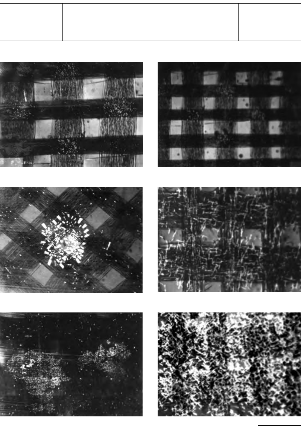
Degree
3
Degree
4
Degree
4
Degree
2
Degree
4
Degree
5
IPC-TM-650
Number
2.1.10
Subject
Visual
Inspection for Undissolved Dicyandiamide
Date
12/94
Revision
A
P
age3of3
DEGREES
OF DICYANDIAMIDE (DICY) CRYSTALS
电子技术应用 www.ChinaAET.com

1 Scope This method describes a procedure for quantifying
the presence of voids in flexible printed board materials.
1.1 Inclusions This test method no longer addresses inclu-
sions which are inspected using ASTM D-149.
2 Applicable Documents and Terms and Definitions
2.1 Applicable Documents
2.1.1 IPC
1
IPC-4202 Flexible Base Dielectrics for Use in Flexible Printed
Circuitry
IPC-4203 Cover and Bonding Material for Flexible Printed
Circuitry
IPC-4204 Flexible Metal-Clad Dielectrics for Use in Fabrica-
tion of Flexible Printed Circuitry
2.1.2 American Society for Testing and Materials
(ASTM)
2
ASTM D-149 Standard Test Method for Dielectric Break-
down Voltage and Dielectric Strength of Solid Electrical Insu-
lating Materials at Commercial Power Frequencies
2.2 Terms and Definitions
2.2.1 Void (Bubble/Hole)
The absence of any substances
in a localized area.
3 Specimens Each specimen: 30 cm x 30 cm [approx. 12
in x 12 in].
4 Test Equipment
4.1
A shear, paper cutter or similar cutting tool for cutting
30 cm X 30 cm [12 in X 12 in] samples.
4.2 Microscope or optical inspection device capable of up to
30X magnification.
4.3 Etching system capable of removal of metal cladding.
4.4 Chemical etchant capable of metal removal without det-
rimental effect to either the adhesive or dielectric.
4.5 Suitable light table for inspecting 30 cm x 30 cm
[approx. 12 in x 12 in] samples.
5 Procedure
5.1 Test Specimen Preparation
Three test specimens
30 cm x 30 cm [approx. 12 in x 12 in] in size are to be pre-
pared for examination/inspection. If the specimens are metal
clad, the metal foil is to be 100% removed by chemical etch-
ing, followed by rinsing and drying. If the specimens are
adhesive-coated on one or both sides, the protective cover
sheet(s) is/are to be completely removed.
5.2 Test Specimen Examination Using the light table and
30X magnification microscope or optical inspection device,
inspect 100% of each of the three 30 cm x 30 cm [approx.
12 in x 12 in] test specimens for voids. Measure and record
the number of voids found, along with the longest dimension
of each void to the nearest 0.013 mm [500 µin], which is con-
sidered to be the size of the void.
Record the size in mm [in], quantity, and type of void found
(bubble, hole, etc.). The requirements for number and size of
the voids are defined in the appropriate materials specifica-
tions: IPC-4202, IPC-4203 or IPC-4204.
1. www.ipc.org
2. www.astm.org
3000 Lakeside Drive, Suite 309S
Bannockburn, IL 60015-1249
IPC-TM-650
TEST METHODS MANUAL
Number
2.1.13
Subject
Inspection for Voids in Flexible Printed Board
Materials
Date
05/12
Revision
B
Originating Task Group
Flexible Circuits Test Methods Subcommittee
(D-15)
Material in this Test Methods Manual was voluntarily established by Technical Committees of IPC. This material is advisory only
and its use or adaptation is entirely voluntary. IPC disclaims all liability of any kind as to the use, application, or adaptation of this
material. Users are also wholly responsible for protecting themselves against all claims or liabilities for patent infringement.
Equipment referenced is for the convenience of the user and does not imply endorsement by IPC.
Page1of1

1.0
Scope
This
method is intended to cover all mechanical
dimension inspections typically referenced on a Printed Board
drawing. This will cover non-optically enhanced measurement
techniques which are not covered by IPC-TM-650, Method
2.2.2.
2.0
Applicable Documents
ANSI NCSL Z540
International
Calibration Standards or
Physical Constants
3.0
Test Specimens
The
test specimen(s) shall be defined
in the applicable performance specification or standard.
4.0
Apparatus or Material
4.1
Mechanical
measurement gage capable of sufficient
accuracy precision and resolution to accomplish the neces-
sary measurement (i.e., calipers, micrometers, pin gages,
templates, etc.).
4.2
All
mechanical measurement gages shall be calibrated in
accordance with ANSI NCSL Z540, International Calibration
Standards or Physical Constants.
5.0
Procedure
5.1
Gages which use an origin based system (i.e., calipers,
micrometers) shall be initialized at the origin.
5.2
Operate
the gage in a manner consistent to obtain the
accuracy, repeatability, and precision required.
5.3 If
the attribute to be measured can vary across the
printed board, multiple measurements must be made to char-
acterize the variation within the sampled area (i.e., hole sizes,
thickness).
5.4
Read
and record the dimensions for the attribute(s)
measured using the same number of significant digits speci-
fied by the drawing, standard, or specification as a minimum
or maximum limiting value.
6.0 Notes
The
following items can affect the test results.
Tool wear & maintenance
Environment effects
Delicacy of gages – proper storage
Improper calibration
The
Institute for Interconnecting and Packaging Electronic Circuits
2215 Sanders Road • Northbrook, IL 60062
IPC-TM-650
TEST
METHODS MANUAL
Number
2.2.1
Subject
Mechanical
Dimensional Verification
Date
8/97
Revision
A
Originating Task Group
Rigid Board T.M. Task Group, 7-11d
Material
in this Test Methods Manual was voluntarily established by Technical Committees of the IPC. This material is advisory only
and its use or adaptation is entirely voluntary. IPC disclaims all liability of any kind as to the use, application, or adaptation of this
material. Users are also wholly responsible for protecting themselves against all claims or liabilities for patent infringement.
Equipment referenced is for the convenience of the user and does not imply endorsement by the IPC.
P
age1of1
电子技术应用 www.ChinaAET.com