IPC-TM-650 EN 2022 试验方法.pdf - 第227页
5.3.3 Within 90 seconds of applying the tape, remove the tape with a steady motion by pulling at a 180 ° angle. 5.3.4 Inspect the lattice pattern under illumination for removal of coating from the substrate. Rate the adh…
1.0
Scope
This
test method establishes a procedure for
determining whether the adhesion of a polymer coating to an
inorganic or ceramic substrate is above an adequate level.
The substrate may or may not have an oxide layer on the sur-
face. The test can be inverted and used for determining the
adhesion of a metal coating to a polymer film.
2.0
Applicable Documents
ASTM D 3330
Test
Method for Peel Adhesion of Pressure-
Sensitive Tape of 180° Angle
ASTM
D 3359
Standard
Test Methods for Measuring Adhe-
sion by Tape Test
3.0
Test Specimen
The
test specimen shall consist of the
coated substrate. A control should also be prepared using a
mutually agreed upon material whose results from this test are
known, preferably a material with an adhesion classification of
5. At least 3 test specimens should be prepared for each
material of interest.
4.0
Apparatus or Material
4.1
25
mm [1.0 in] wide semitransparent pressure sensitive
tape with an adhesion strength of 43 ± 6 g/mm [38 ± 5 oz/in].
The adhesion should not change more than 6.5% of its mean
value within 12 months. 3M Scotch brand #600 tape has
been found to be acceptable for this test.
4.2
Rubber
eraser on end of pencil.
4.3
A
light source is helpful in determining if the cut has
been made all the way through the polymer to the substrate.
4.4
A
closed boiling water bath.
5.0
Procedure
5.1
Preparation
of test specimen. Refer to ASTM D 3330
and ASTM D 3359.
5.1.1
Prepare
and clean the substrate according to the
manufacturer’s recommended procedure.
5.1.2 Prime
the surface with the manufacturer’s recom-
mended adhesion promoter, if required.
5.1.3
Apply
a 10 µmto25µm (measured after processing
is complete) coating onto the surface of the substrate using
the manufacturer’s recommended procedure.
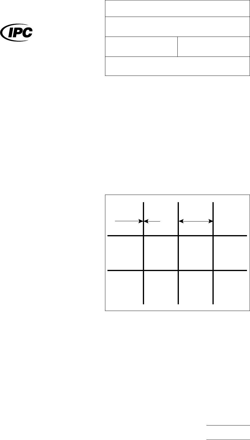
5.2
Pattern Coating
The
coating should be patterned
according to the procedures outlined in section 4.2.5 of IPC-
DD-135. The pattern consists of a 10 x 10 grid of 1 mm x 1
mm squares separated by 100 µm wide lines or pattern fea-
tures, as illustrated in Figure 1. At least two complete grids
must be patterned on the specimen, one for the initial test and
one for the 3 hour test.
5.3
Test
5.3.1
Remove
two complete laps of tape and discard.
Remove an additional length at a steady (not jerked) rate and
cut a piece approximately 75 mm [3.0 in] long.
5.3.2
Place
the center of the tape over one of the grid pat-
terns and smooth into place by a finger. Rub the tape firmly
with the eraser on the end of the pencil to ensure good con-
tact between the tape and the film. The color under the tape
is a good indicator of contact between the tape and the film.
2.4.1.6-01
Figure
1
1 mm100
µ
m
The
Institute for Interconnecting and Packaging Electronic Circuits
2215 Sanders Road • Northbrook, IL 60062-6135
IPC-TM-650
TEST
METHODS MANUAL
Number
2.4.1.6
Subject
Adhesion,
Polymer Coating
Date
7/95
Revision
Originating Task Group
Deposited Dielectric Task Group (C-13a)
Material
in this Test Methods Manual was voluntarily established by Technical Committees of the IPC. This material is advisory only
and its use or adaptation is entirely voluntary. IPC disclaims all liability of any kind as to the use, application, or adaptation of this
material. Users are also wholly responsible for protecting themselves against all claims or liabilities for patent infringement.
Equipment referenced is for the convenience of the user and does not imply endorsement by the IPC.
P
age1of2
电子技术应用 www.ChinaAET.com
5.3.3
Within
90 seconds of applying the tape, remove the
tape with a steady motion by pulling at a 180° angle.
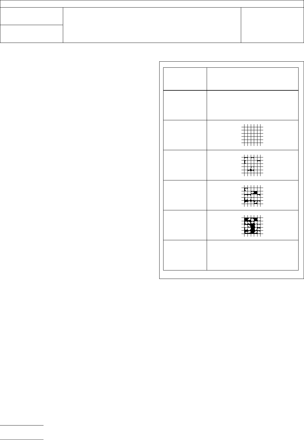
5.3.4
Inspect the lattice pattern under illumination for
removal of coating from the substrate. Rate the adhesion in
accordance with the following scale illustrated in Figure 2:
•5 The edges of the line patterns are completely smooth;
none of the squares of the lattice are detached.
•4 Small flakes of the coating are detached at the intersection
of the lattice; less than 5% of the area is affected.
•3 Small flakes of the coating are detached along the edges
and at intersections of the lattice. The area affected is 5 to
15% of the lattice.
•2 The coating has flaked along the edges and on parts of
the squares. The area affected is 15 to 35% of the lattice.
•1 The coating has flaked along the edges of the line patterns
in long ribbons and whole squares have detached. The
area affected is 35 to 65% of the lattice.
•0 Greater than 65% of the lattice has detached.
5.3.5
Place
the test specimens in a boiling water bath and
stress the samples for 3 hours. The water in the boiling water
bath must completely cover the test specimens for the entire
3 hours. A closed system that returns the steam as conden-
sation is preferred.
5.3.6
Remove
the test specimens from the boiling water
bath or environmental chamber and allow to cool to room
temperature.
5.3.7
Wipe
sample dry. Repeat steps 5.3.1-5.3.4 on the
second (unused) grid pattern.
5.3.8
Report
adhesion results for both the initial and 3 hour
tests.
6.0 Notes
None
2.4.1.6-02
Figure
2
Classification
5
None
4
3
2
1
0 Greater than 65%
Surface of cross-cut area from
which flaking has occurred.
(Example for six paralleled cuts)
IPC-TM-650
Number
2.4.1.6
Subject
Adhesion,
Polymer Coating
Date
7/95
Revision
P
age2of2
电子技术应用 www.ChinaAET.com

1
Scope
Ductility
values are determined by measuring the
bulge height on a Mullen bulge tester or equivalent. Measure-
ments are made in mm.
2
Applicable Documents
None
3
Test Specimen
Three
clean, smooth pieces of copper
foil 10 cm x 10 cm area or any non-overlapping equivalent
areas.
4
Apparatus
Mullens
Bulge Tester by B. F. Perkins & Son,
Inc., Model A to be 10 RPM at large shaft between gear box
and diaphragm, or equivalent.
5
Procedure
5.1 Preparation
Raise
upper clamping ring by rotating the
hand wheel. Place a 10 cm x 10 cm by 0.15 mm thick steel
plate that is perfectly flat over the diaphragm and lower the
upper clamping ring applying sufficient pressure to prevent
slippage. Zero the dial indicator. Raise the upper clamping
ring and remove the 10 cm x 10 cm by 0.15 mm steel plate.
NOTE:
The
above operation should be done once every
eight-hour shift.
Start the motor and move the ball-handled control lever to the
right to be certain that the diaphragm is returned to its start-
ing position.
5.2
Test
5.2.1
Place a sample of the copper foil to be tested over the
diaphragm with the matte side up.
5.2.2
Lower
the clamping ring, applying sufficient pressure
to prevent slippage of the sample between the plates.
5.2.3 Move
the ball-handled control lever to the left. The
operator should keep his hand on the lever in readiness to
stop or reverse the machine at any time during the test and
when the test is complete. During the test, the operator
should be watching the dial indicator and, at the instant burst-
ing occurs, should note the reading on the dial indicator and
the ball-handled control lever should be moved as far to the
right as it will go and be released. This will return the dia-
phragm to its starting position and automatically shut off the
pump.
5.3
Evaluation
5.3.1
Record
the reading from the dial indicator.
5.3.2
Rotate
the hand wheel to raise the clamping ring and
remove the sample. Avoid overlapping of the clamping areas
and disregard any single reading that is not reasonably con-
sistent with those taken in neighboring areas, and repeat the
test.
The
Institute for Interconnecting and Packaging Electronic Circuits
2215 Sanders Road • Northbrook, IL 60062-6135
IPC-TM-650
TEST
METHODS MANUAL
Number
2.4.2
Subject
Ductility
of Copper Foil
Date
3/76
Revision
A
Originating Task Group
N/A
Material
in this Test Methods Manual was voluntarily established by Technical Committees of the IPC. This material is advisory only
and its use or adaptation is entirely voluntary. IPC disclaims all liability of any kind as to the use, application, or adaptation of this
material. Users are also wholly responsible for protecting themselves against all claims or liabilities for patent infringement.
Equipment referenced is for the convenience of the user and does not imply endorsement by the IPC.
P
age1of1
电子技术应用 www.ChinaAET.com