IPC-TM-650 EN 2022 试验方法.pdf - 第743页
IPC-3408-3-1 Figure 1 Interconnection Resistance T est Assembly; Flex to ITO Glass 0.4 mm Flex, 9 x 25 mm 9.0 mm x 2.5 mm nom. ZAF, 0.025 mm, 3.2 x 10 mm Bonded Test Sample 0.2 mm line/space Pitch Flex-ITO Glass Test Sam…

1
Scope
The
purpose of these tests is to characterize
changes in individual interconnection resistances as a function
of exposure time in various environmental aging conditions for
both flex to PWB and flex to indium-tin-oxide (ITO) coated
glass bonds.
2
Applicable Documents
IPC-3408
General
Requirements for Anisotropically Conduc-
tive Adhesive Films
3
Test Specimens
3.1
0.2
mm line/space test boards
0.2 mm line/space flex test circuits
4
Apparatus
4.1
ITO
coated soda-lime glass test slides, 20 ohms/sq. mm
4.2
Polypropylene
trays for sample storage in chamber
4.3
Instrumentation
to permit four-probe resistance mea-
surement
4.5
Required
environmental test chamber(s):
a) Thermal aging,
100°C
b) Thermal cycling,
-55°C to >125°C,
five hour period
c) Humidity aging,
60°C/95% RH
5
Procedure
5.1 Sample Preparation
5.1.1
Cut
the flex test circuits to the appropriate length (see
Figure 1 and Figure 2). If flex board samples are being pre-
pared, all traces on the flex should be shorted together on one
end.
5.1.2
Use
of new PCB is recommended. If new boards are
being used, there should be no need for any special cleaning
procedure. If used boards are to be used, they should be
inspected to ensure that:
a) Protective metalization (Au or Pb-Sn) is intact.
b) FR-4 isn’t significantly discolored from prior high tempera-
ture exposure.
c) The board is free of any residue from previous tests.
5.1.3
Refer
to 5.2 for proper bonding procedure.
5.2
Sample Procedure
5.2.1
Prepare
at least three test samples for each test con-
dition to be run. For the flex board case, it is possible to
mount two test samples on each board. Refer to IPC-3408 for
proper bonding procedure.
5.2.2
After
bonding is completed, each sample should be
identified by a test number. Test numbers should be written
on the test substrate using an indelible marker.
5.2.3 Clamp
the unbonded end of the flexible circuit to the
matching board traces to make electrical contact, with an
elastomeric compliant layer behind the flex to maintain uniform
contact force.
5.2.4
Initial
interconnection resistances should be measured
and recorded. The recommended measurement technique is
illustrated in Figure 3. This technique can be used with either
test sample type.
Note:
This
technique doesn’t allow for the measurement of
the first and last circuit trace. There are 15 measurements to
be made on each sample.
5.2.5
Samples
should be placed in the polypropylene trays,
and the trays placed in the appropriate chamber. The time
and date should be noted for the purpose of computing
elapsed time.
5.2.6
Samples
should be removed from the chambers for
resistance measurement after 24-hour, one-week, three-
week, and six-week time points. All environmental tests are
considered complete after six weeks. Samples should be
allowed to equilibrate at ambient conditions for at least 30
minutes prior to measurement.
5.2.7
All
resistance data should be tabulated and/or graphed
to facilitate proper interpretation of the results.
2215
Sanders Road
Northbrook, IL 60062-6135
IPC-TM-650
TEST
METHODS MANUAL
Number
2.6.24
Subject
Junction
Stability Under Environmental Conditions
Date
11/98
Revision
Originating Task Group
SMT Mounting Adhesives Task Group (5-24d)
Material
in this Test Methods Manual was voluntarily established by Technical Committees of the IPC. This material is advisory only
and its use or adaptation is entirely voluntary. IPC disclaims all liability of any kind as to the use, application, or adaptation of this
material. Users are also wholly responsible for protecting themselves against all claims or liabilities for patent infringement.
Equipment referenced is for the convenience of the user and does not imply endorsement by the IPC.
P
age1of3
ASSOCIA
TION CONNECTING
ELECTRONICS INDUSTRIES
电子技术应用 www.ChinaAET.com
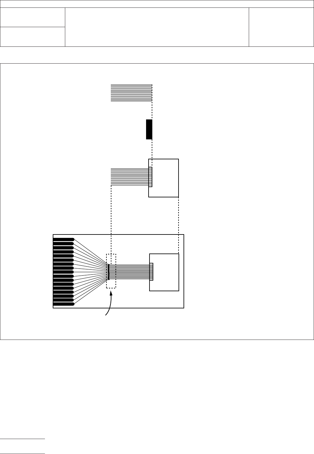
IPC-3408-3-1
Figure
1 Interconnection Resistance Test Assembly; Flex to ITO Glass
0.4 mm Flex, 9 x 25 mm
9.0 mm x 2.5 mm nom.
ZAF, 0.025 mm, 3.2 x 10 mm
Bonded Test Sample
0.2 mm line/space
Pitch Flex-ITO Glass
Test Sample Clamped
to 0.4 mm Pitch Test Board
Clamp
IPC-TM-650
Number
2.6.24
Subject
Junction
Stability Under Environmental Conditions
Date
11/98
Revision
P
age2of3
电子技术应用 www.ChinaAET.com
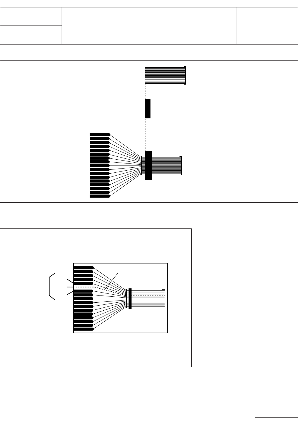
IPC-3408-fig4
Figure
3 Four Probe Interconnect Resistance Measurement Technique for
Flex to PWB and Flex to ITO Glass
VI
Ih, Vh
I1
R1= AV/I
6th trace
IPC-3408-fig3
Figure
2 Interconnection Resistance Test Assembly; Flex to PWB
0.4 mm Flex, Shortened on End
17 Traces, 9 mm x 25 mm
ZAF, 0.050 mm, 3.2 mm x 10 mm
Bonded Test Sample
0.2 mm line/space
Pitch Flex Board
IPC-TM-650
Number
2.6.24
Subject
Junction
Stability Under Environmental Conditions
Date
11/98
Revision
P
age3of3
电子技术应用 www.ChinaAET.com