IPC-TM-650 EN 2022 试验方法.pdf - 第95页
T able 2 T est Report on Solder Paste Enter appropriate information in top portion of report and complete report by entering the test results or checkmarks in the appropriate spaces. Inspection Purpose: QPL I.D. Number: …
1.0
Scope
This
test method is designed to determine the
maximum (average) solder particle size in a solder paste using
a fineness of grind gauge.
2.0 Applicable Documents
ASTM D-1210-79
Fineness
of Dispersion of Pigment-Vehicle
Systems
3.0
Test Specimen
At
least 100 grams of uniformly mixed
solder paste.
4.0
Equipment/Apparatus
Gauge-Hegman
Type CMA
185*, or equivalent, in accordance with ASTM D1210-79. A
hardened steel, stainless steel, or chrome-plated steel block
approximately 175 mm in length, 65 mm in width, and 13 mm
thick.
The top surface of the block shall be ground smooth and flat
and shall contain one or two grooves 140 mm in calibrated
length and 12.5 mm wide parallel to the longer sides of the
block.
Each groove shall be tapered uniformly in depth lengthwise
from a suitable depth (for example 50 to 100 micrometers) at
10 mm from one end to zero depth at the other with interme-
diate calibrations in accordance with the depth at these
points.
Scraper—A single- or double-edged hardened steel, stainless
steel, or chrome-plated steel blade 90 mm long, 38 mm wide,
and 6.4 mm thick. The edge or edges on the long sides shall
be straight and rounded to a radius of approximately 0.38
mm.
5.1
Test
5.1.1
Using
a fineness of grind gauge (Hegman) Type CMA
185 or equivalent in accordance with ASTM D-1210 deter-
mine the maximum and average particle size of the powder.
5.2
Evaluation
Acceptance
of each type of powder shall
be based on the specifications listed in Table 1. Enter the
results in Table 2 ‘‘Test Report on Solder Paste.’’
*Source:
Precision Gage & Tool Co. 28 Volkenand Ave., Dayton, Ohio
45410 513/254-8404
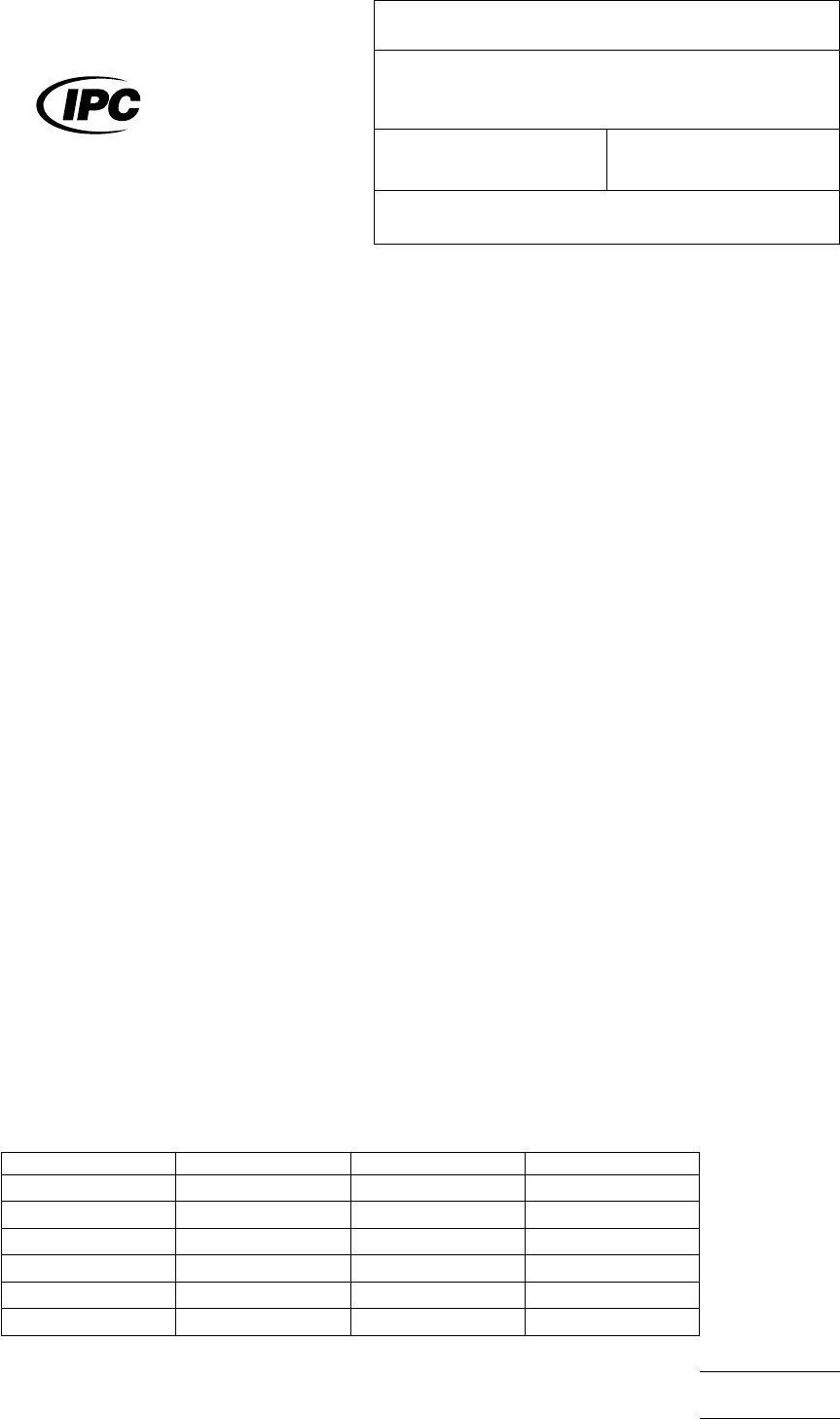
T
able 1
1st
4th Major
T
ype 1 160µm 150 µm 140 µm
Type 2 80µm 75 µm 65 µm
Type 3 50µm 45 µm 40 µm
Type 4 40µm 38 µm 35 µm
Type 5 30µm 25 µm 23 µm
Type 6 20µm 15 µm 15 µm
The
Institute for Interconnecting and Packaging Electronic Circuits
2215 Sanders Road • Northbrook, IL 60062
IPC-TM-650
TEST
METHODS MANUAL
Number
2.2.14.3
Subject
Determination
of Maximum Solder Powder Particle
Size
Date
1/95
Revision
Originating Task Group
Solder Paste Task Group (5-24b)
Material
in this Test Methods Manual was voluntarily established by Technical Committees of the IPC. This material is advisory only
and its use or adaptation is entirely voluntary. IPC disclaims all liability of any kind as to the use, application, or adaptation of this
material. Users are also wholly responsible for protecting themselves against all claims or liabilities for patent infringement.
Equipment referenced is for the convenience of the user and does not imply endorsement by the IPC.
P
age1of2
电子技术应用 www.ChinaAET.com
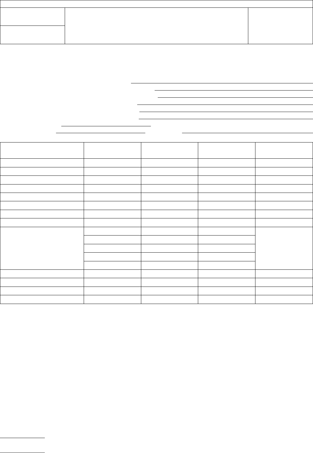
T
able 2 Test Report on Solder Paste
Enter appropriate information in top portion of report and complete report by entering the test results or checkmarks in the appropriate spaces.
Inspection Purpose: QPL I.D. Number:
__
Qualification Manufacturer’s Identification:
__ Quality Conformance A Manufacturer’s Batch Number:
__
Quality Conformance B Date of Manufacture:
__
Shelf-Life Extension Original Use-By Date:
__
Performance Revised Use-By Date:
Date
Inspection Completed:
Overall
Results: __ Pass __ Fail
Inspection Performed by:
W
itnessed by:
Inspections
User’s
Actual
Requirement Test Result P/F (*) Tested by & Date
Material
Visual
Metal Content
Viscosity
Solder Ball
Slump
Alloy
Flux
Powder Size
% In Top Screen
% In Next Screen
% In Bottom Screen
% In Receiver Bottom
Max. Powder Size
Powder Shape
Tack
Wetting
* P/F = PASS/FAIL; enter P if test results are within tolerance of actual requirement; otherwise, enter F
IPC-TM-650
Number
2.2.14.3
Subject
Determination
of Maximum Solder Powder Particle Size
Date
1/95
Revision
P
age2of2
电子技术应用 www.ChinaAET.com

1
Scope
This
method defines the procedure for determin-
ing the roughness or profile of metallic foils.
1.1
The
surface finish or roughness of foils shall be evalu-
ated using R
a
.R
a
is
defined as the arithmetic average value of
all absolute distances of the roughness profile from the center
line within the measuring length.
1.2
The
foil profile of foils shall be evaluated using the
parameter R
Z
(DIN)
or R
TM
,
which is defined as the average
maximum peak to valley height of five consecutive sampling
lengths within the measurement length. This value is approxi-
mately equivalent to the values of profile determined from
microsectioning techniques.
1.3
R
Z
(ISO)
is a different parameter from R
Z
(DIN)
and is not
applicable to this method.
2
Applicable Documents
DIN 4768
ISO 4287
3 Test Specimens
Cut
a specimen 101 x 101 mm [4 x 4
in] minimum from the representative sample. The location and
number of specimens shall be defined in the material specifi-
cation.
4
Apparatus/Materials
4.1
Knife
or other suitable device.
4.2
Profilometer
or surface roughness meter with a motor-
ized drive and the following parameters:
Parameter Value
Cut Off 0.8 mm
Measuring Length 4.0 mm
Tracing Length <5 mm
Diamond Stylus Radius 0.005 mm
Roughness Parameter
R
a
,
per 1.1
R
ZDIN
or
R
TM
,
per 1.2
Note: See Footnote No. 1 for equipment found suitable for
determination of both R
a
and
R
ZDIN
(or
R
TM
).
1
4.3
Roughness Standard
Smooth
Side: R
a
with
5% or better certified tolerance
Treated Side: R
DZIN
(or
R
TM
)
with 5% or better certified toler-
ance
4.4
Plate
glass or other smooth flat surface
4.5
Compressed
air
4.6
Gloves,
lint free
4.7
Tape
or weight
5
Procedure
5.1
Check
the profilometer calibration using the appropriate
roughness standard for the value R
a
or
R
ZDIN
(R
TM
)
and mag-
nitude to be measured. Insure the stylus moves perpendicular
to the grooves and the surface.
Note: For R
Z
measurements,
known standards are available in
1, 3 and 10 micrometer nominal values. See footnote 2.
2
5.1.1
Compare
the values obtained on six different mea-
surements taken at different locations within the standard to
the certified (not nominal value) of the standard. If the average
result is not within 2% of the standard value, adjust the instru-
ment and repeat 5.1 until this tolerance is achieved.
5.2
Place
the foil test specimen on the plate glass surface
with the side to be tested away from the glass. Secure the
specimen with tape or a weight at both ends to prevent move-
ment or buckling during the measurement.
1.
Profilometers which have been used to measure both R
a
and
R
Z
or
R
TM
are:
Surtronic 3 by Taylor Hobson (R
a
and
R
TM
)
(see 8.2); M4P by Perthen (see 8.1) (R
a
and
R
ZDIN
).
2.
Standards for R
DZIN
are
available from: see 8.1, PGN-3 3 micrometer nominal, PGN-10 10 micrometer nominal.
2215 Sanders Road
Northbrook, IL 60062-6135
IPC-TM-650
TEST
METHODS MANUAL
Number
2.2.17A
Subject
Surface
Roughness and Profile of Metallic Foils
(Contacting Stylus Technique)
Date
2/2001
Revision
A
Originating Task Group
Metallic Foils Task Group (3-12A)
Material
in this Test Methods Manual was voluntarily established by Technical Committees of IPC. This material is advisory only
and its use or adaptation is entirely voluntary. IPC disclaims all liability of any kind as to the use, application, or adaptation of this
material. Users are also wholly responsible for protecting themselves against all claims or liabilities for patent infringement.
Equipment referenced is for the convenience of the user and does not imply endorsement by IPC.
P
age1of2
ASSOCIA
TION CONNECTING
ELECTRONICS INDUSTRIES
电子技术应用 www.ChinaAET.com