IPC-TM-650 EN 2022 试验方法.pdf - 第773页
IPC-2627-5-3 Figure 5-3 245 °C Nominal Reflow Profile Chart* * The times to t1, t2 and t3 may vary based on the mass of the sample test specimen. IPC-TM-650 Number 2.6.27 Subject Thermal Stress, Convection Reflow Assembly …
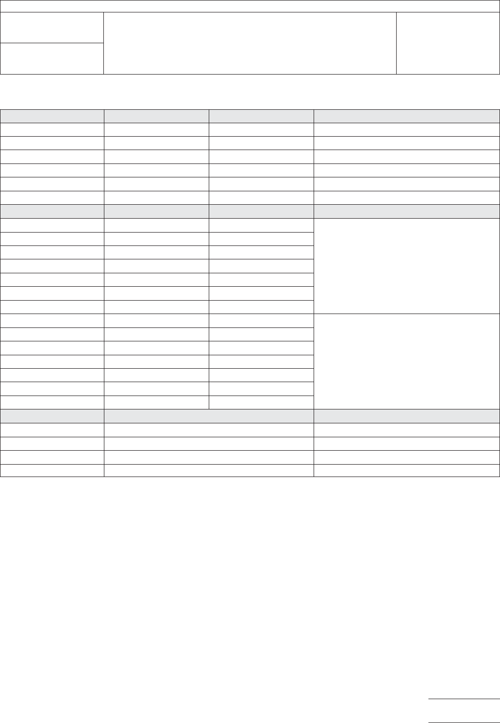
Table 5-3 245 °C Nominal Reflow Profile Specifications*
Value Time (Seconds) Temperature (°C) Description
t1 198 ± 15 – Target preheat time
t2 254 ± 10 – Target peak reflow time
t3 311 ± 15 – Target cool-down start time
t3 - t1 113 ± 30 – Target time above T1
T1 – 217 Maximum preheat temperature
T2 – 245 ± 5 Target reflow temperature
Point Time (Seconds) Temperature (°C) Description
A030
Upper specification limit values
B 94 217
C 184 217
D 240 250
E 269 250
F 325 217
G 518 30
H3030
Lower specification limit values
I 148 88
J 212 217
K 245 240
L 264 240
M 297 217
N 361 30
Segment Slope (°C / second) Description
A-B & I-J 2.0 Maximum preheat rate
H-I 0.5 Minimum preheat rate
F-G -1.0 Minimum cool-down rate
M-N -3.0 Maximum cool-down rate
IPC-TM-650
Number
2.6.27
Subject
Thermal Stress, Convection Reflow Assembly Simulation
Date
2/2020
Revision
B
Page7of10
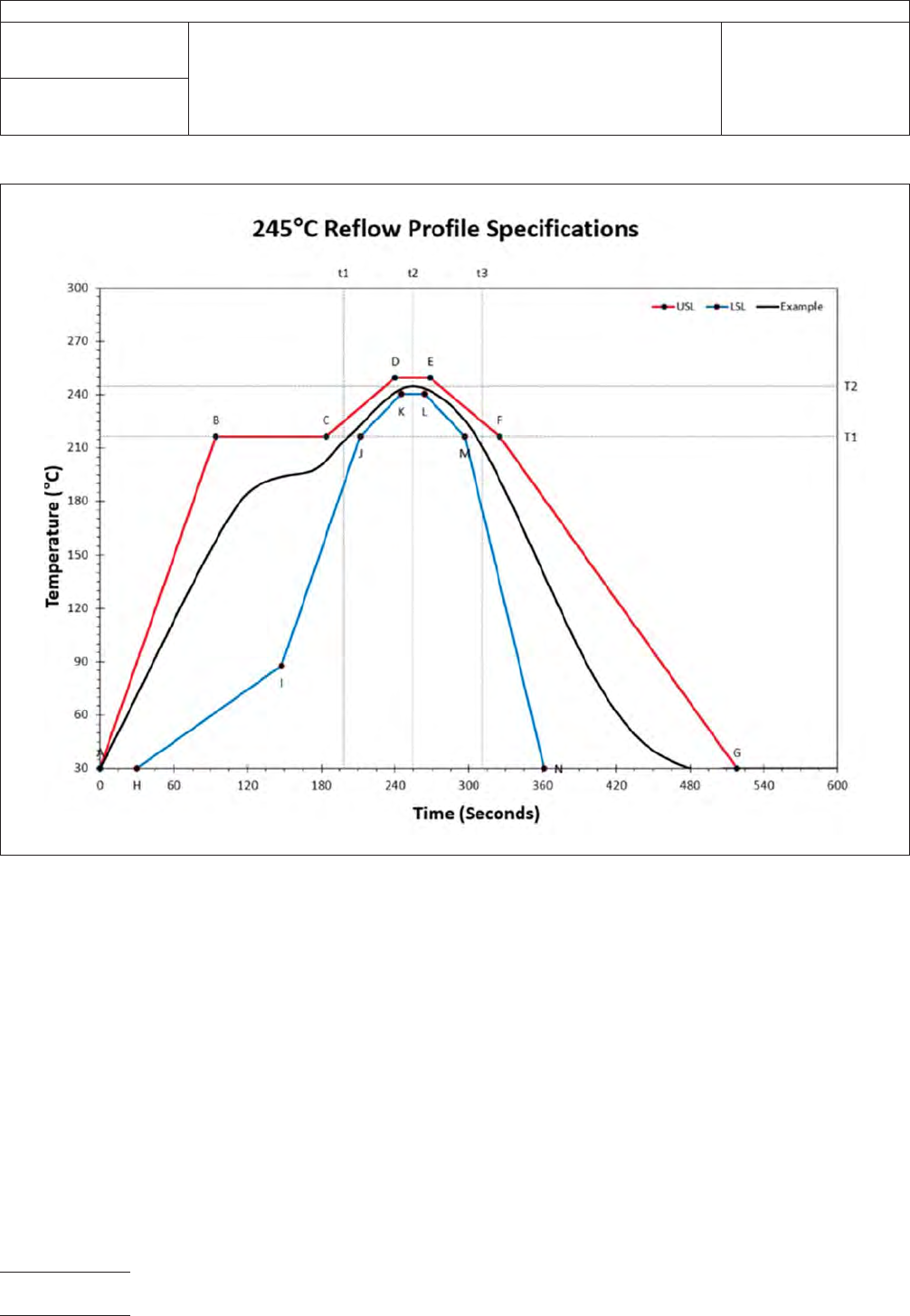
IPC-2627-5-3
Figure 5-3 245 °C Nominal Reflow Profile Chart*
* The times to t1, t2 and t3 may vary based on the mass of the sample test specimen.
IPC-TM-650
Number
2.6.27
Subject
Thermal Stress, Convection Reflow Assembly Simulation
Date
2/2020
Revision
B
Page8of10

5.3 Evaluation
5.3.1 Microsection
The test specimen shall be microsec-
tioned when this test method is used for thermal stress prior
to structural integrity evaluation. After the test specimen has
been conditioned and reflowed in accordance with the
requirements of 5.1 and 5.2, microsection the test specimen
in accordance with IPC TM-650 Method 2.1.1. Inspect speci-
mens required for microsection (e.g., A, B, A/B, AB/R, etc.) for
compliance to the applicable performance specification
and/or AABUS requirement.
Note: For guidelines on microsection preparation see IPC-
9241.
5.3.2 Resistance Change Resistance change shall be
used to evaluate IPC-2221 Appendix A (latest revision)
D-coupons for performance-based evaluation of the samples
when specified. Microsectioning of D coupons which have
been evaluated by resistance change is not required.
5.3.2.1 Percent change in resistances of each sample’s
nets shall be determined using the first cycle’s peak tempera-
ture resistance as the reference.
5.3.2.2 The maximum allowable percent change in resis-
tance after the test specimen has been conditioned and
reflowed in accordance with 5.1 and 5.2 shall be 5% maxi-
mum unless otherwise specified.
5.3.2.3 Cycles to failure, corresponding percent change of
the failure, and the percent change of the final cycle shall be
documented.
5.3.3 Deviations to the stated requirements or additional
requirements defined here shall be AABUS.
6 Notes
6.1
The design of the convection reflow system should be
flexible enough to facilitate the creation of the reflow profiles
depicted in Figure 5-1, Figure 5-2 and Figure 5-3 for all the
applicable test specimen designs encountered. Some issues
to consider are as follows:
• Thermal mass compensation capability (energy vs. time)
• Environmental control capability (heating and cooling)
• Reproducibility of parameters
• Preheat
• Conveyor speed (if applicable)
• Heating ramp rate
• Cool down rate
• Programming capability
• Profile memory
The IPC-TM-650 website provides a non-comprehensive list-
ing of providers of convection reflow systems suitable for
meeting the reflow profiles within this test method.
6.2 Deviations to the time and temperature specified in 5.1.1
should take into consideration maintaining the solderability of
the surface finish being utilized.
6.3 Example Drawing Notes As this method addresses
assembly issues with printed boards, it is recommended that
the user of the printed board establish a drawing note in the
procurement documentation to provide the printed board fab-
ricators with guidance relative to the intended reflow process
of the printed board. An example of such a drawing note is
provided as follows:
A. IPC D COUPONS SHALL BE DESIGNED IAW IPC-2221
APPENDIX A AND SHALL INCLUDE COMPONENT (A),
VIA (B) AND ALL PROPAGATED B STRUCTURES. X OF
EACH COUPON DESIGN SHALL BE TESTED PER
MANUFACTURING PANEL.
B. THE IPC D COUPONS SHALL BE SUBJECTED TO 6
REFLOW SIMULATIONS IAW IPC-TM-650, METHOD
2.6.27 USING THE [230 °C, 245 °C, OR 260 °C] PRO-
FILE. ACCEPTANCE CRITERIA SHALL BE<5%
CHANGE IN RESISTANCE.
IPC-TM-650
Number
2.6.27
Subject
Thermal Stress, Convection Reflow Assembly Simulation
Date
2/2020
Revision
B
Page9of10