IPC-TM-650 EN 2022 试验方法.pdf - 第634页
air solenoid by actuating the UUT’s finger switch or foot switch. Repeat these operations, fine-adjusting the oscillo- scope for best display of any transient peaks for a minimum of three measurable trials. 5.3 Calculati…
Non-US
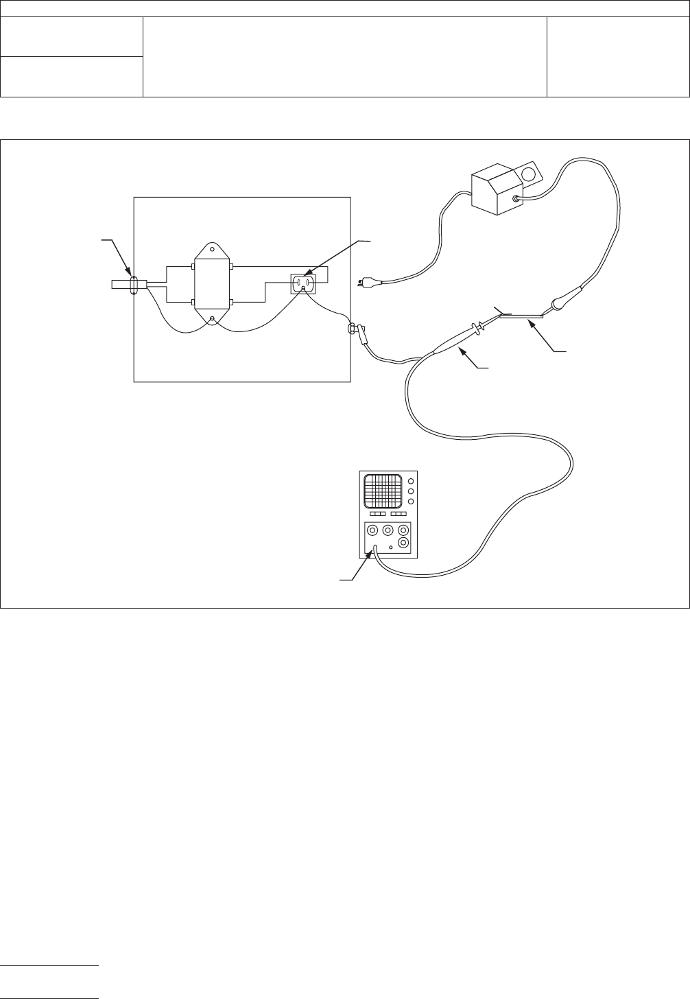
power receptacles may be different from those illus-
trated.
4.7
Calibration and Standardization
The
oscilloscope
(vertical and horizontal amplifiers) shall bear a current calibra-
tion sticker. The scope probe shall be adjusted/compensated
to display the square wave calibration signal generated by the
oscilloscope without undershoot or overshoot.
5
Procedure
5.1 Baseline Measurement
Turn
on the UUT and allow it
to warm up to a normal operating temperature. Touch the hot
tip to the tinned area of the test electrode. Apply solder to
form good electrical contact. Turn off the UUT. Adjust the
oscilloscope controls as required and record any ambient sig-
nals that are displayed by the oscilloscope. Attempt this for a
minimum of two minutes. Repeat this baseline test for a mini-
mum of three trials. If any ambient transients are greater than
1.5 V peak, measures must be taken to reduce the effects of
the ambient interference to below 1.5 V peak.
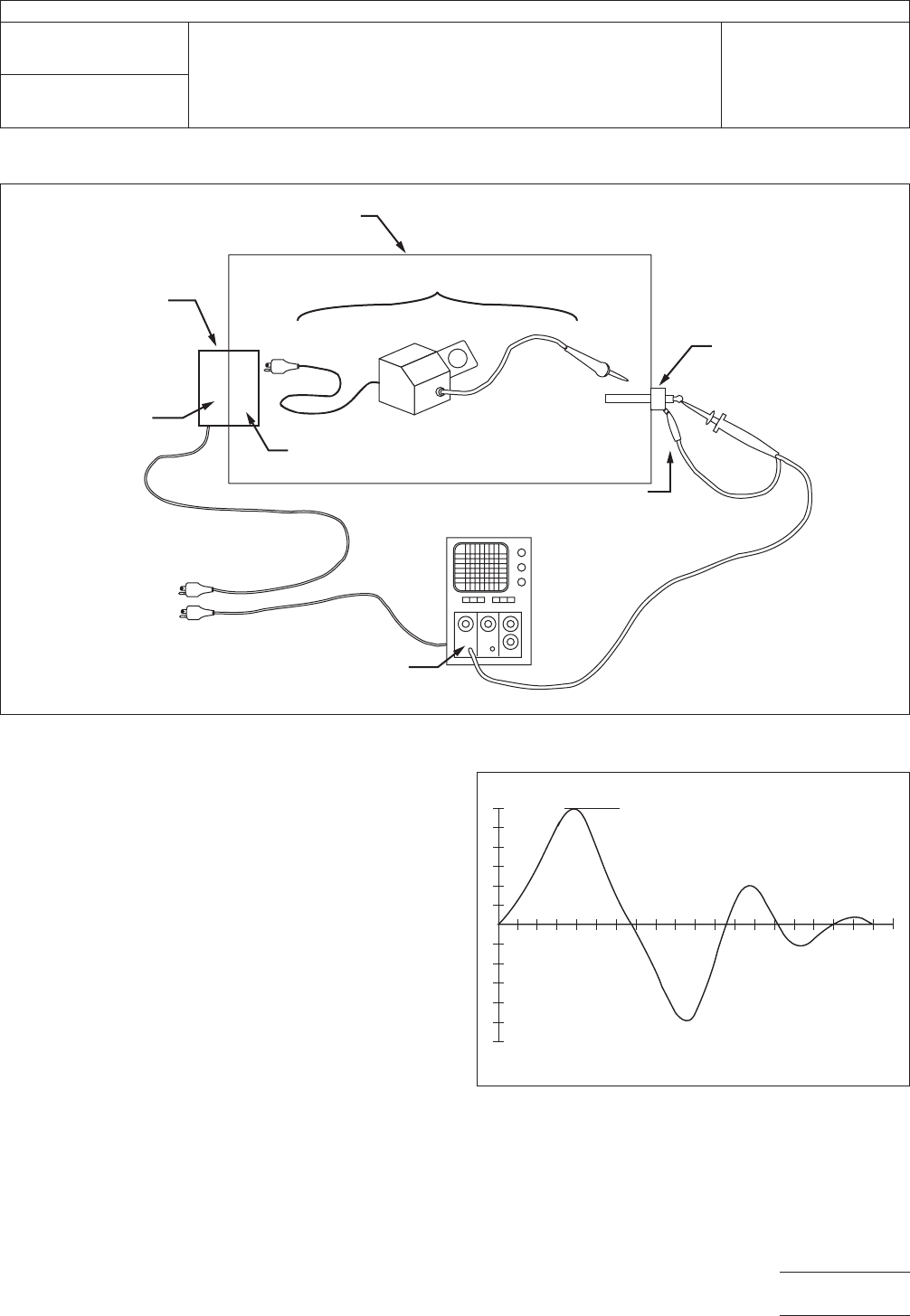
Place the UUT in a screen room or the shielded enclosure (see
Figure 2) if the test is to be conducted in a shielded enclosure.
If the shielded enclosure is utilized, arrange for support and/or
remote movement of the handpiece. Configure the UUT for
typical operation. In cases where function switches must be
operated, arrange for remote switch actuation, such as by
using a non-metallic rod through a small hole in the enclosure.
Position the tip of the handpiece for remote placement onto
the test electrode.
5.2
Test Measurement
Turn
on the UUT. Let the tip dwell
on the electrode while the UUT cycles power to maintain tem-
perature for a minimum of two minutes. Operate various other
functions of the UUT if present, such as the vacuum pump or
IPC-2.5.33.2-1
Figure
1 Apparatus for Transient Measurement
OSCILLOSCOPE
AC LINE
FIL
TER ASSEMBLY
1 MEGOHM
INPUT
RECEPTACLE
FOR UUT
UUT
10 MEGOHM
(X10) SCOPE
PROBE
TEST
ELECTRODE
STRAIN
RELIEF
TO
AC
AC
LINE
FILTER
METAL BOX
BLK BLK
WHTWHT
GRN GRN
GRN
IPC-TM-650
Number
2.5.33.2
Subject
Measurement
of Electrical Overstress from Soldering Hand
Tools - Transient Measurements
Date
11/98
Revision
P
age2of4
电子技术应用 www.ChinaAET.com
air
solenoid by actuating the UUT’s finger switch or foot
switch. Repeat these operations, fine-adjusting the oscillo-
scope for best display of any transient peaks for a minimum
of three measurable trials.
5.3
Calculation and Interpretation of Results
Record
the
peak amplitude (see Figure 3). All three measurement tri-
als must have peak voltages ≤ 2.0 volts.
The peak voltage shall be ≤ ± 2.0 volts.
6 Notes
If
tracking test results, record the measured values
on a copy of the form found in Method 2.5.33.
6.1
Oscilloscope Adjustments
A
good initial setup for the
oscilloscope was found to be as shown in Table 1.
It’s important to start from a position of low trigger sensitivity
and work toward high sensitivity. If one were to start with high
sensitivity, weak transients would trigger the oscilloscope
before the strong, more potentially damaging ones.
6.2
Discussion of Transients.
Transients
are generated
by voltage or current switching in the UUT. Switching typically
occurs in circuits that modulate heaters, drive LED displays,
IPC-2.5.33.2-2
Figure
2 Alternate Apparatus for Transient Measurement
AC POWER
BULKHEAD
AC
LINE
FIL
TER
JUNCTION BOX
WITH RECEPTACLE
1 MEGAOHM
INPUT
OSCILLOSCOPE
SHIELDED ENCLOSURE
UNIT
UNDER TEST
TEST
ELECTRODE
GROUND
CLIP
ELECTRODE
BULKHEAD
10 MEGAOHM
(X10) SCOPE
PROBE
IPC-2.5.33.2-3
Figure
3 Transient Waveform Measurement
VPEAK
IPC-TM-650
Number
2.5.33.2
Subject
Measurement
of Electrical Overstress from Soldering Hand
Tools - Transient Measurements
Date
11/98
Revision
P
age3of4
电子技术应用 www.ChinaAET.com

and
control motor-pumps and solenoids. To facilitate observ-
ing or capturing a transient event, the UUT should be oper-
ated in such a manner where switching takes place. The UUT
should be brought to a state where heater power is cycling
off-and-on. Heaters that are running at 100% duty cycle (con-
stantly on) may not generate any measurable transients. For
UUTs that incorporate relays, solenoids, or motors the UUT’s
functions should also be operated in such a manner where
these devices energize and de-energize.
As the UUT is cycled, the oscilloscope’s trigger should be
adjusted to a more sensitive setting until a transient causes a
trigger. The event may have to be repeated as the oscillo-
scope’s storage controls are re-adjusted for best picture.
Sometimes the event has a peak amplitude better observed
on a different vertical scale.
T
able 1 Oscilloscope Setup
V
ertical 500 mv/div. DC coupling
Horizontal 100 ns/div.
Trigger Source
Level
Mode
Internal
Full cw or ccw rotation
(large peaks cause trigger)
single sweep
Polarity + or -
Storage (for analog scopes) fast
variable persistence
auto erase
IPC-TM-650
Number
2.5.33.2
Subject
Measurement
of Electrical Overstress from Soldering Hand
Tools - Transient Measurements
Date
11/98
Revision
P
age4of4
电子技术应用 www.ChinaAET.com