IPC-TM-650 EN 2022 试验方法.pdf - 第314页
the isotherm is reached. In this case, the temperature at the time of failure shall be recorded. 5.4 Report 5.4.1 Report the Time to Delamination as determined in 5.3. Report the time at which any other plot event has ta…

1.0
Scope
This
method describes the method for deter-
mining the time to delamination of laminates and printed
boards through the use of a thermomechanical analyzer
(TMA).
2.0
Applicable Documents
IPC-TM-650
Method
2.4.24, Glass Transition Temperature
and Z-Axis Thermal Expansion by TMA.
3.0
Test Specimens
3.1 Size
Specimens
shall be approximately 6.35 mm x
6.35 mm [0.25 in x 0.25 in] by the thickness of the sample.
3.2
Quantity and Sampling
Unless
otherwise specified,
two specimens shall be tested, to be taken from random loca-
tions of the material in question.
4.0
Apparatus or Material
4.1 Drying Chamber
Air
circulating oven capable of main-
taining 105 ±2°C [221 ±3.6°F].
4.2
Cutting Equipment
Diamond
blade or wheel, sanding
equipment, or equivalent, to provide a specimen of the size
and edge quality specified.
4.3
Desiccator
Dessication
chamber capable of maintain-
ing an atmosphere less than 30% RH at 23°C [73.4°F].
4.4
Tester
Thermal
Mechanical Analyzer (TMA) capable of
determination of dimensional change to within ±0.0025 mm
[0.0001 in] over the specified temperature range.
5.0
Procedure
5.1 Specimen Preparation
5.1.1
Metallic
clad laminates shall be tested as is. Multilayer
printed boards may be sampled with internal conductors
present. (For determination of a multilayer board’s bond integ-
rity, presence of internal conductors is preferred.)
5.1.2
Specimens
shall be cut to the specified size using
appropriate procedures and equipment to minimize mechani-
cal stress or thermal shock.
5.1.3 The
edges shall be smooth and burr-free by means on
sanding or equivalent (to allow the specimen to rest com-
pletely flat on the mounting stage). Use care to minimize
stress or heat on the specimen.
5.1.4
The
specimen shall be preconditioned by baking for 2
hours at 105 ±2°C [221 ±3.6°F], then cooled to room tem-
perature in a dessicator.
5.2
Measurement
5.2.1
Remove
the specimen from the dessicator and place
the specimen on the stage of the TMA taking care that the
sample is centered and resting flat on the stage.
5.2.2
Lower
the TMA’s probe onto the specimen and apply
a force of 0.005 Newtons [5g]; then lower the furnace into
place around the stage.
5.2.3
Start
the temperature ramp (or scan) from an initial
temperature no higher than 35°C [95°F].
5.2.4
Maintain
the scan at the specified rate. Unless other-
wise specified, the scan rate shall be 10°C/minute (see 6.4).
5.2.5 After
the scan reaches the specified isothermal tem-
perature, hold at that temperature for 10 minutes or to failure.
Unless otherwise specified, the isothermal temperature shall
be 260°C [500°F].
If the instrument allows real time display of the data, terminate
the experiment after evidence of delamination is displayed.
5.3
Evaluation
The
time to delamination is determined as
the time from the onset of the isotherm to failure. Failure is any
event or deviation of the data plot where the thickness is
shown to have irreversibly changed. The scan in Figure 1 is
typical of an epoxy material at 260°C [500°F] isothermal tem-
perature. On occasion, some materials will delaminate before
The
Institute for Interconnecting and Packaging Electronic Circuits
2215 Sanders Road • Northbrook, IL 60062-6135
IPC-TM-650
TEST
METHODS MANUAL
Number
2.4.24.1
Subject
Time
to Delamination (TMA Method)
Date
12/94
Revision
Originating Task Group
MIL-P-13949 Test Methods Task Group (7-11b)
Material
in this Test Methods Manual was voluntarily established by Technical Committees of the IPC. This material is advisory only
and its use or adaptation is entirely voluntary. IPC disclaims all liability of any kind as to the use, application, or adaptation of this
material. Users are also wholly responsible for protecting themselves against all claims or liabilities for patent infringement.
Equipment referenced is for the convenience of the user and does not imply endorsement by the IPC.
P
age1of2
电子技术应用 www.ChinaAET.com
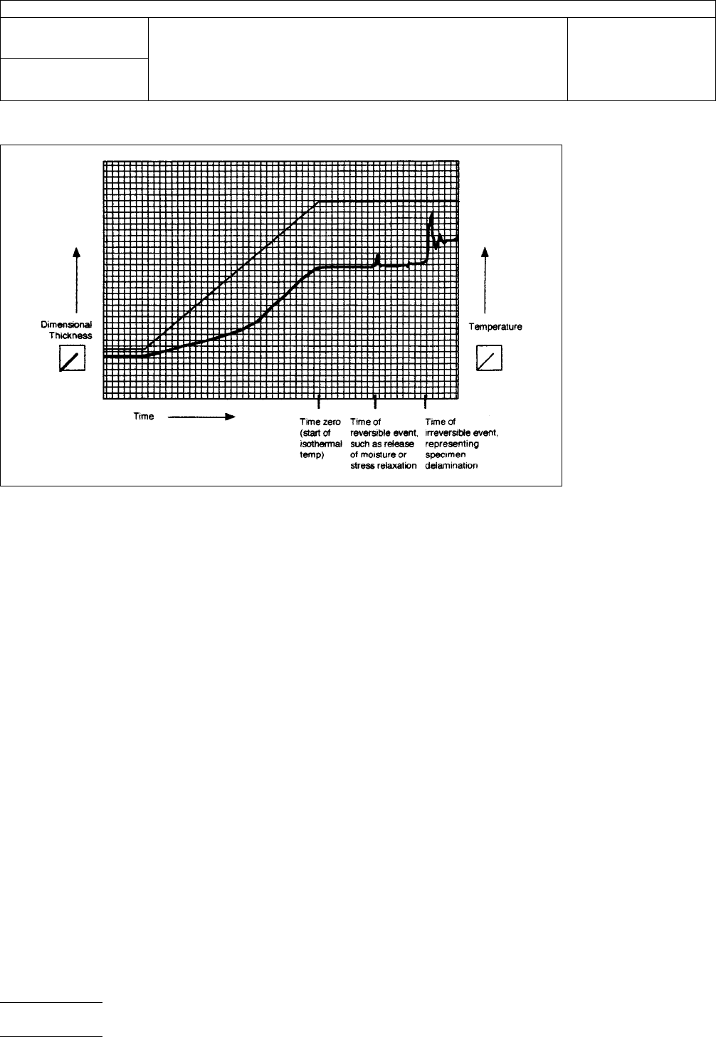
the
isotherm is reached. In this case, the temperature at the
time of failure shall be recorded.
5.4
Report
5.4.1
Report
the Time to Delamination as determined in 5.3.
Report the time at which any other plot event has taken place
which was not determined to be irreversible.
5.4.2
Report
the configuration of the sample (e.g., whether
external or internal foil is present).
5.4.3 Report
the ramp rate and isothermal temperature if
other than that specified.
6.0
Notes
6.1
For
epoxy laminates and similar materials, the recom-
mended isothermal temperature is 260°C [500°F]. For polyim-
ides and other high temperature materials, the isothermal
temperature may be increased to 288°C [550°F]. For other
material types, consult with the material manufacturer.
6.2
Calibration
of the instrument should be carried out
according to the manufacturer’s instructions.
6.3
The
T
g
of
the material may be obtained from this test,
which is similar to Method 2.4.24. It should be noted that the
T
g
so
obtained is a ‘‘first pass’’ value.
6.4
A
faster ramp rate will decrease the time to run, provide
some greater distinction between materials, and provide a
closer equivalence to the Thermal Stress test, 2.4.13.1.
A rate of 100°C/minute [212° F/minute] is recommended for
such determinations.
Figure
1
IPC-TM-650
Number
2.4.24.1
Subject
Time
to Delamination (TMA Method)
Date
12/94
Revision
P
age2of2
电子技术应用 www.ChinaAET.com
1.0
Scope
This
test method establishes a procedure for
determining the glass transition temperature of organic films
using dynamic mechanical analysis (DMA).
2.0
Applicable Documents
ASTM D 618
Standard
Practice for Conditioning Plastics and
Electrical Insulating Materials for Testing
3.0
Test Specimen
The
test specimen shall consist of a
strip 22.5 mm long and 6.25 mm wide with a minimum thick-
ness of 5 µm. The analysis is based on the assumption of a
constant specimen geometry, therefore the test specimens
must be stiff enough not to plastically deform during the
experiment.
4.0
Apparatus or Material
Rheometrics
Solids Analyzer
Model RSA-II with a film/fiber fixture or equivalent.
5.0
Procedure
5.1
The
test specimens should be conditioned at 23 ± 2°C
and 50 ± 5% relative humidity for not less than 24 hours prior
to testing. Refer to ASTM D 618.
5.2
Follow
the manufacturer’s recommendations for equip-
ment startup and calibration.
5.3 Mount
the specimen in the film/fiber fixture. Make certain
that the specimen is mounted perpendicular to the clamps.
Hand tighten the clamps as much as possible to prevent
specimen slippage during a run.
5.4
Operate
at a frequency of 1 Hz (6.28 radians/sec). Heat
the specimen in dry nitrogen at a rate of no faster than 2°C/
min., or in steps of 5°C increments, in dry air.
5.5
When
the transition has been observed, heat at least
50°C beyond the apparent completion of the thermal activity
before returning to initial conditions.
5.6
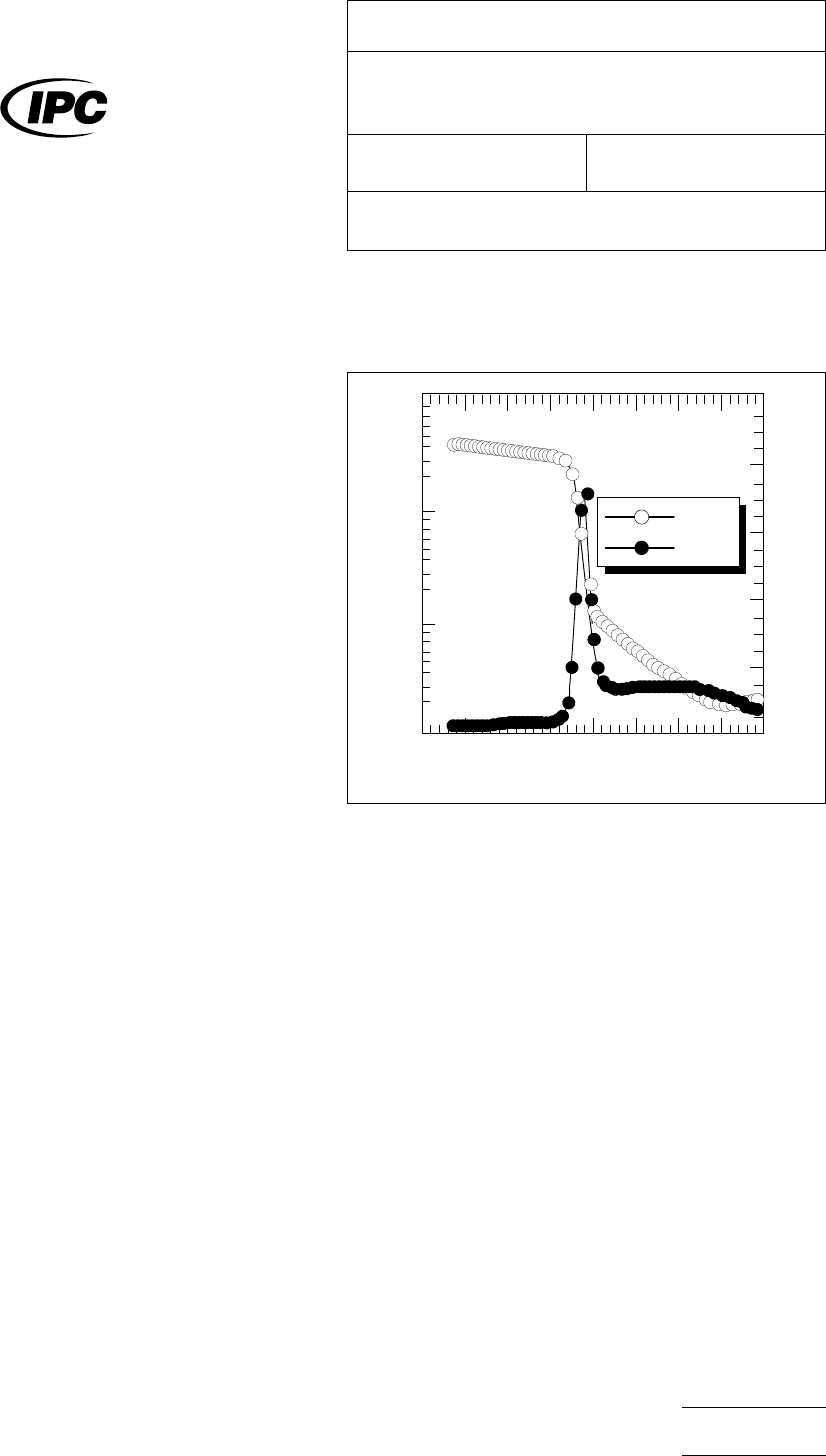
The
glass transition temperature is defined as the tem-
perature corresponding to the maximum in the tan δ vs. tem-
perature curves at a frequency of 1 Hz. Tan δ is calculated
from
tan δ= E’’/E’
where E’’ is the loss modulus and E’ is the storage modulus.
A typical plot is shown in Figure 1.
5.7
Report
both the glass transition (maximum in tan δ), e.g.,
200°C (DMA-1 Hz), and the temperature range over which the
storage modulus (E’) changes (i.e., the transition range), e.g.,
transition range: 160-205°C.
6.0
Notes
6.1
Calibration
of the instrument must be carried out
according to the manufacturer’s recommendations with at
least one standard being indium.
6.2
The
glass transition temperature for a given material will
be significantly different depending on the method of analysis
(i.e, DMA, DSC, or TMA). The glass transition determined by
DMA is frequency dependent and increases with increasing
frequency. The glass transition determined by DSC or TMA
will depend on the heating rate. The test method used along
with the frequency (DMA) or heating rate (DSC or TMA) should
be noted beside the glass transition value, e.g., 135°C
(DMA-1 Hz) or 141°C (DSC-5°C/min).
2.4.24.2-01
Figure
1
Temperature (°C)
E
1
(dynes/cm
2
)
10
11
10
10
10
9
10
8
0
50 100 150 200 250 300 350 400
0.0
0.2
0.4
0.6
0.8
1.0
TAN δ
E
1
TAN δ
200°C
The
Institute for Interconnecting and Packaging Electronic Circuits
2215 Sanders Road • Northbrook, IL 60062-6135
IPC-TM-650
TEST
METHODS MANUAL
Number
2.4.24.2
Subject
Glass
Transition Temperature of Organic Films −
DMA Method
Date
7/95
Revision
Originating Task Group
Deposited Dielectric Task Group (C-13a)
Material
in this Test Methods Manual was voluntarily established by Technical Committees of the IPC. This material is advisory only
and its use or adaptation is entirely voluntary. IPC disclaims all liability of any kind as to the use, application, or adaptation of this
material. Users are also wholly responsible for protecting themselves against all claims or liabilities for patent infringement.
Equipment referenced is for the convenience of the user and does not imply endorsement by the IPC.
P
age1of2
电子技术应用 www.ChinaAET.com