IPC-TM-650 EN 2022 试验方法.pdf - 第627页
6.4 Test Results Complete ALL shaded areas. Description of UUT (brand, model configuration, etc.): T est Procedure Pass/Fail Criteria V alue Recorded Status Ground Measurements (2.5.33.1) ≤ 5 ΩΩ [ Pass [ Fail T ransient …
•
Junction overheated due to excessive forward current
6.2
Limits to Prevent Voltage Breakdown Due to Indi-
vidual Transients
As
integrated circuit geometries shrink,
dielectric breakdown voltage ratings also diminish. One semi-
conductor discussed here (battery operated integrated cir-
cuits) currently represents the lowest breakdown ratings.
S-MOS Systems’ SMC62L35 single-chip microcomputer is
designed to run from a single 1.5 volt battery. It has an abso-
lute maximum voltage (damage could result) of 2 volts.
The recommended limit for individual transients is 2 volts
peak.
6.3
Limits to Prevent Overheating Due to Steady-State
Leakage
Most
semiconductor junctions are intentionally
designed, but in integrated circuits, there are also unavoidable
intrinsic junctions. Also, there are junctions that are never sup-
posed to be operated in the forward direction (i.e., JFETs and
tuning diodes). The devices are not well character-ized by the
manufacturer regarding the maximum forward current.
Regardless of the nature of the junction, simultaneous forward
current and voltage drop results in power dissipation. If the
junction power results in a sufficient temperature increase, the
junction may be changed or destroyed. It is possible to pre-
vent forward current from flowing through a junction simply by
keeping the applied voltage below the forward junction volt-
age rating. Two semiconductors discussed here represent the
lowest forward junction voltage ratings: Schottky diodes and
germanium diodes. Motorola’s MBD201 Schottky diode and
most common germanium diodes begin to conduct at 220
millivolts. The test method apparatus represents these by
including commonly available 1N34 germanium diodes. To be
sure no junction heating can be caused by the UUT, the cur-
rent should be zero. But practically, since zero is difficult to
measure, a 1 microamp maximum tolerance can be permitted
without fear of overheating the junction. The recommended
limit for current leakage is 1 microamp (flowing through a
closed circuit, which includes parallel head-to-tail germanium
diodes).
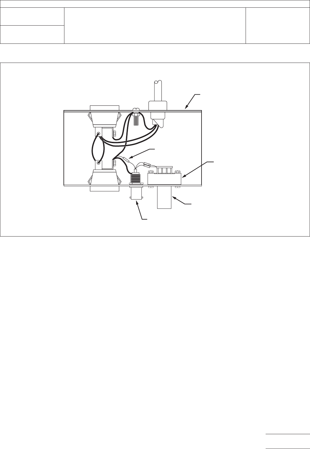
IPC-2.5.33-1
Figure
1 Current Leakage Test Circuit Configuration
AC RECEPT
ACLE
FOR VOLTMETER
AC RECEPTACLE
FOR UUT
BNC CONNECTOR
FOR VOLTMETER
TEST ELECTRODE
CARD EDGE
CONNECTOR
1K RESISTOR
METAL BOX
DIODES
GRN
BLK
WHT
TO
AC
IPC-TM-650
Number
2.5.33
Subject
Measurement
of Electrical Overstress from Soldering Hand
Tools
Date
11/98
Revision
P
age3of5
电子技术应用 www.ChinaAET.com
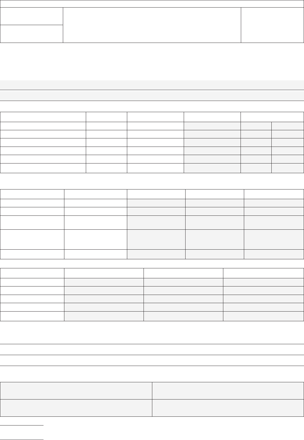
6.4
Test Results
Complete
ALL shaded areas.
Description
of UUT (brand, model configuration, etc.):
T
est Procedure Pass/Fail Criteria Value Recorded Status
Ground
Measurements (2.5.33.1) ≤5 ΩΩ[ Pass [ Fail
Transient Measurements/Pass 1 (2.5.33.2) ≤2 V peak V [ Pass [ Fail
Transient Measurements/Pass 2 (2.5.33.2) ≤2 V peak V [ Pass [ Fail
Transient Measurements/Pass 3 (2.5.33.2) ≤ 2 V peak V [ Pass [ Fail
Current Leakage Measurements (2.5.33.3) ≤1.0 µ-amp DC µ-amp DC [ Pass [ Fail
Current Leakage Measurements (2.5.33.3) ≤1.0 µ-amp ACrms µ-amp ACrms [ Pass [ Fail
Description of Test Equipment and Configuration
Equipment
Function Brand Model Calibration Date
AC
millivoltmeter true mvAC/rms
DC millivoltmeter 60 mv DC
Ohmmeter resistances beyond 5
MΩ
Storage Oscilloscope 100 Mhz bandwidth or
faster, 1 MΩ input
vertical amplifier
Constant Current Source 10 milliamps DC
Equipment
Scale Used Cal / Std Meas. Baseline Meas.
AC
millivoltmeter
DC millivoltmeter
Ohmmeter
Storage Oscilloscope
Constant Current Source
Additional Comments:
Test
Completed by:
NAME:
DATE:
COMPANY: PHONE:
IPC-TM-650
Number
2.5.33
Subject
Measurement
of Electrical Overstress from Soldering Hand
Tools
Date
11/98
Revision
P
age4of5
电子技术应用 www.ChinaAET.com

6.5
Reference
MIL-STD-1686
1
Electrostatic
Discharge Control Program for
Protection of Electrical and Electronic Parts, Assemblies and
Equipment (Excluding Electrically Initiated Explosive Devices)
MIL-HDBK-263
Electrostatic
Discharge Control Handbook
for Protection of Electrical and Electronic Parts, Assemblies
and Equipment (Excluding Electrically Initiated Explosive
Devices)
EOS/ESD-S6.0-1994
2
Grounding
- Recommended Practice
1.
Standardization Documents Order Desk, 700 Robbins Avenue, Bldg. 4D, Philadelphia, PA 19111-5094
2. ESD Association, 7902 Turin Rd., Ste. 4, Rome, NY 13440-2069
IPC-TM-650
Number
2.5.33
Subject
Measurement
of Electrical Overstress from Soldering Hand
Tools
Date
11/98
Revision
P
age5of5
电子技术应用 www.ChinaAET.com