IPC-TM-650 EN 2022 试验方法.pdf - 第431页
5.4.2 Record the capacitance of the air filled cell as C 1 to the nearest .01 pf (or nearest .001 pf if the 0-20 pf scale is used). 5.4.3 Remove the specimen from the humidity controlled environment. 5.4.4 Insert the fir…

4.3
Test Leads
2
RG 58/U coax cables approximately
304.8 mm [12 in] long with suitable connectors for the bridge.
One lead shall have a banana plug (high lead) and the low lead
should have a GR874
3
at
the cell end. (Note: The use of a
G874-QBJA
4
instead
of the standard GR874 will permit a
BNC
5
connector
to be used for the cell connection of the low
lead, reducing the chances of damaging the 874 connector.)
4.4
Flask
with stopper (for silicone fluid storage).
4.5
Beaker
for cell overflow.
4.6
Funnel.
4.7
Filter
paper (coarse).
4.8
1
Centistoke Dow Corning 200 Fluid (500 ml minimum).
Note: Fluid must be at the same ambient temperature as the
test cell and should be stored in close proximity to the test
cell.
4.9
Forceps
or large tweezers.
5.0
Procedure
5.1 Conditioning
All
materials which are affected by mois-
ture, including all reinforced laminates and most films, should
be conditioned at 23°C ± 2°C50±5% RH for a minimum of
24 hours prior to testing. If required by the specification,
specimens may be tested after humidity or water immersion
or tested after desiccation.
5.2
Test Conditions
For
ambient temperature tests the
temperature should be 23°C ± 2°C.
Note: Variation should not exceed 1°C during the test. Ambi-
ent humidity is not critical for most materials. The exception is
very thin, very hydroscopic material such as polyimide film,
where moisture content may be well over 1%. Such material
must be tested at the desired humidity since the dielectric
constant will increase measurably with moisture content and
changes may occur very rapidly after removal from a con-
trolled environment. For materials which experience glass
transitions in the room temperature region, e.g., PTFE, some
acrylics, the temperature should be 23°C ± 1°C.
5.3
Set Up
5.3.1
Open
the electrode on the cell. Blow out the cell using
clean compressed air to remove any dust or silicone fluid.
5.3.2
Warm
up the bridge for at least the minimum amount
of time recommended by the manufacturer.
5.3.3
Attach
the low lead to the guarded electrode of the
cell and the bridge.
5.3.4
Attach
the high lead to the bridge and place the
banana plug in the vicinity of, but not touching, the banana
plug jack of the test cell.
Note: Be certain the shielding on the high lead does not con-
tact the banana plug.
5.3.5
Set
the bridge up on appropriate ranges:
Capacitance: 200 pf (or 100 pf)
Conductance: microsiemens
0-2 PTFE and very low loss material.
0-20 Epoxy and other moderate loss materials.
0-200 Some phenolic and very high loss materials.
Note: For very thick specimens >3.18 mm [>0.125 in] the 0 to
20 pf range can often be used, increasing the precision of the
measurement. All values must be obtained on the same range
for both capacitance and conductance.
5.3.6
Set
the cell spacing on the LD-3 to approximately
125% of the material thickness 0.51 mm minimum to 7.62
[0.020 in minimum to 0.3 in] Note: The spacing may be as
little as 10% or as much as 50% greater than specimen thick-
ness without a significant effect on results.
5.3.7
Zero
the bridge for both capacitance and conduc-
tance.
5.4
Measurement
5.4.1
Connect
the banana plug of the high lead to the cell.
3.
GR874—Catalogue #874-9414 Gilbert Engineering, Glendale, AZ, (602) 245-1050
4. G874-QBJA—Catalogue #874 QBJA Gilbert Engineering, Glendale, AZ
5. BNC—Catalogue #999-225 Amphenol
IPC-TM-650
Number
2.5.5.3
Subject
Permittivity
(Dielectric Constant) and Loss Tangent (Dissipation
Factor) of Materials (Two Fluid Cell Method)
Date
12/87
Revision
C
P
age2of4
电子技术应用 www.ChinaAET.com

5.4.2
Record
the capacitance of the air filled cell as C
1
to
the
nearest .01 pf (or nearest .001 pf if the 0-20 pf scale is
used).
5.4.3 Remove the specimen from the humidity controlled
environment.
5.4.4
Insert
the first specimen to be tested with the marked
corner remaining in the upper left and the right side of the test
specimen against one side of the test cell. Note: This will
ensure that subsequent measurements are taken using the
same area of the specimen.
5.4.5
Read
and record the value of capacitance with the
specimen in the cell as C
3
.
5.4.6
Remove
the first specimen and obtain C
3
for
any other
specimens to be measured with same cell spacing.
5.4.7
After
removing the last specimen from the cell, fill the
cell with Dow Corning 200 Fluid using the funnel and a filter to
remove any small particles from the fluid and collect any
excess fluid from the overflow pipe on the cell with the small
beaker.
5.4.8
Allow
a few seconds for the temperature of the cell
and fluid to equilibrate and record the capacitance of the liq-
uid filled cell as C
2
.
Note: If
the capacitance is drifting consistently in one direc-
tion, the fluid is not at equilibrium.
5.4.9
Record
the conductance of the fluid filled as cell G
1
.
Note: The
value obtained will vary somewhat with cell spacing
and humidity but should not exceed 500 microsiemen (200
microsiemen if low loss material, with a loss tangent under
.001 is being tested). Values beyond this are generally indica-
tive of problems with the leads, contamination of the fluid or
bridge error and must be corrected if correct dissipation fac-
tor is to be determined.
5.4.10
Insert
the first specimen in the fluid filled cell exactly
as in the dry reading and record the value of the capacitance
as C
4
and
the value of the conductance as G
2
.
Note: Values
should stabilize within a few seconds after speci-
men insertion. If they do not there is very likely air trapped in
the cell. This is quite common if multiple thin specimens are
used to form one test specimen. If this occurs presoaking the
specimen with fluid before immersion and inserting one ply at
a time should eliminate the problem.
5.4.11
Remove
the first specimen and insert each subse-
quent specimen in the same order as the dry values were
obtained and record the C
4
and
G
2
values
for each.
5.4.12 After
the last specimen is measured and removed
from fluid, check and record the values of the capacitance
and conductance.
Note: If the level of the fluid with the specimen removed does
not cover the electrodes, fill the cell before checking the final
values. This check on C
2
will
be used to verify the amount of
influence that changes in ambient temperature have had on
the values obtained.
6.0
Calculation
6.1
Calculate
the value of the permittivity (dielectric constant)
of each specimen tested using the equation:
DK =
1.00058
C1
S
C1
+
(C3−C1)(C2−C1) C4
(C3−C1) C4 −(C4−C2) C3
D
Round
the value obtained to the nearest .01.
6.2
Calculate
the value of the loss tangent (dissipation fac-
tor) of each specimen tested using the equation:
DF =
G2
6.2832
C4
+
S
DK
* .99942 C1−C4
C4−C2
DS
G2
6.2832
C4
−
G1
6.2832
C2
D
Round
the value to the nearest .0001.
Note: Values should be calculated using a computer and must
not be rounded prematurely.
6.3
If
the value of C
2
changed
during the course of the mea-
surements, use the final values of C
2
and
G
2
,
the value of C
1
,
and
the values on the last specimen for C
3
and
C
4
to
recalcu-
late the DK and Df of the final specimen. If the difference in DK
values is significant, the temperature of the cell must be con-
trolled more precisely during the measurement period.
6.4
Calculate
the average permittivity (dielectric constant) (if
more than one specimen was tested).
6.5
Calculate
the average loss tangent (dissipation factor) (if
more than one specimen was tested).
7.0
Report
IPC-TM-650
Number
2.5.5.3
Subject
Permittivity
(Dielectric Constant) and Loss Tangent (Dissipation
Factor) of Materials (Two Fluid Cell Method)
Date
12/87
Revision
C
P
age3of4
电子技术应用 www.ChinaAET.com
7.1
Report
the minimum, maximum and average values of
the permittivity (dielectric constant).
7.2
Report the average value of the loss tangent (dissipation
factor).
7.3 Report the specimen preconditioning, e.g., C-24/23/50.
7.4 Report
the actual test conditions for temperature and
humidity.
7.5
Report
if the specimen was built up.
7.6
Report
the approximate cell spacing.
7.7
Report
any anomalies in the test or variations from the
prescribed procedures or tolerances.
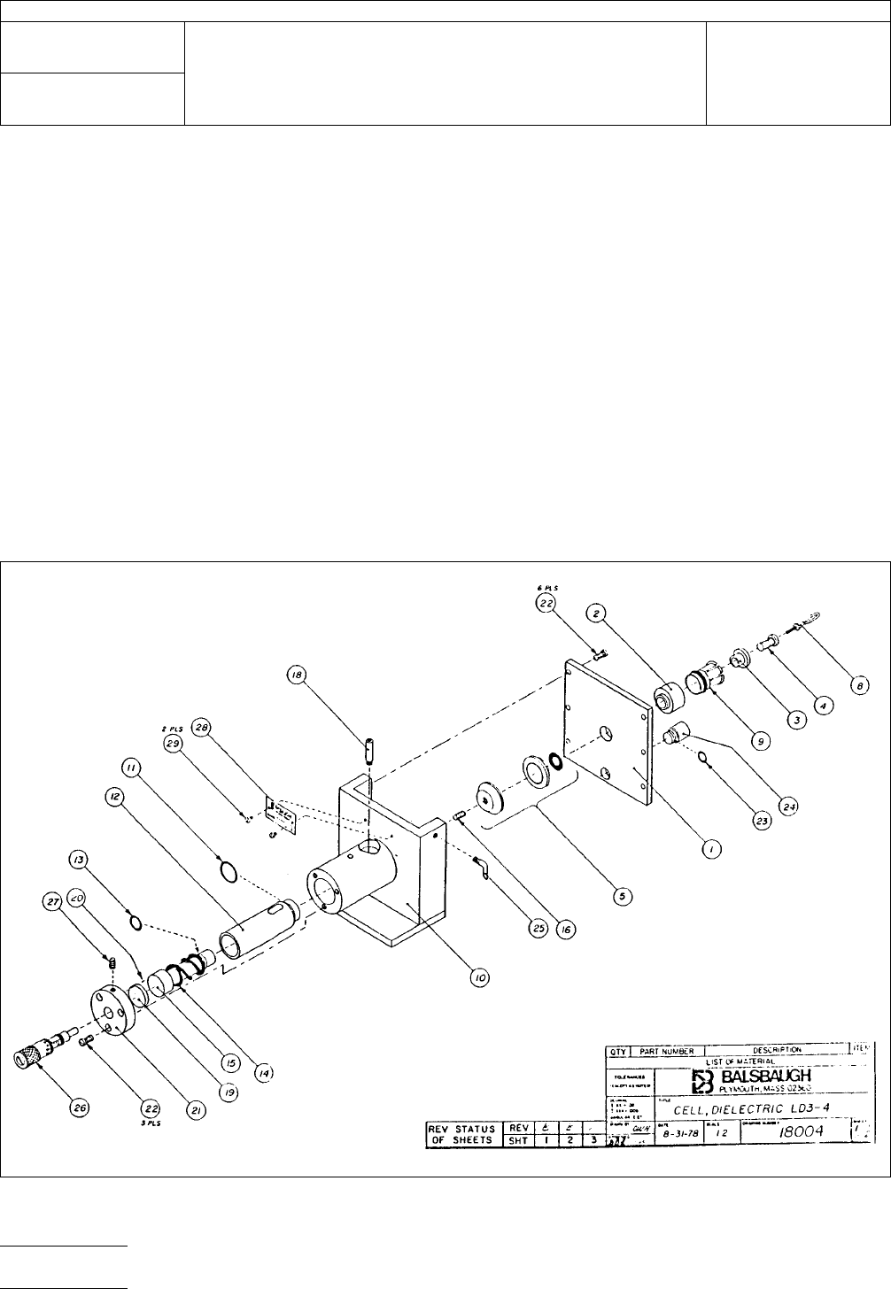
IPC-2553-1
Figure
1
IPC-TM-650
Number
2.5.5.3
Subject
Permittivity
(Dielectric Constant) and Loss Tangent (Dissipation
Factor) of Materials (Two Fluid Cell Method)
Date
12/87
Revision
C
P
age4of4
电子技术应用 www.ChinaAET.com