IPC-TM-650 EN 2022 试验方法.pdf - 第794页
IPC-3-8-4 Figure 4 T olerances for T erminal-Peak Sawtooth Shock Pulse IPC-3-8-5 Figure 5 T olerance Limits for Measuring System Frequency Response IPC-TM-650 Number 3.8 Subject Mechanical Shock, Connectors Date 7/75 Rev…
5.2.2 The test sample shall be connected to the discontinu-
ity monitor and a minimum current of 100 milliamperes shall
be established in the series circuit comprising all contacts of
the test sample.
5.2.3 The test sample shall be subjected to three (3) shocks
in each direction along each of three (3) orthogonal axes (18
shocks total). During and after the application of each shock,
the contacts shall be monitored for discontinuities in excess of
1 microsecond.
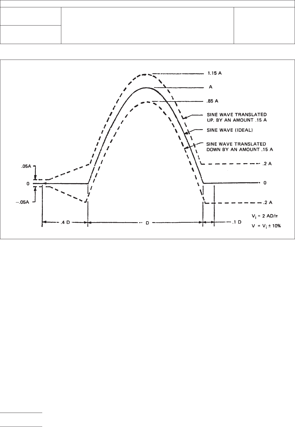
NOTE:
The oscillogram should include a time about 3D long
with the pulse approximately in the center. The integration to
determine the velocity change should extend from 0.4D
before the pulse to 0.1D beyond the pulse. The peak accel-
eration,
magnitude of the sawtooth pulse is P and its duration is D.
Any measured acceleration pulse which can be contained
between the broken line boundaries is nominal terminal-peak
sawtooth pulse of nominal peak value, P, and nominal dura-
tion, D. The velocity-change associated with the measured
acceleration pulse is V.
6.0 Notes
6.1
Acceptance criteria shall be established in terms of one,
or any combination, of the following:
A. Loss of continuity during or after any imposed shock.
B. Mechanical damage,
IPC-3-8-3
Figure 3 Tolerances for Half Sine Shock Pulse
IPC-TM-650
Number
3.8
Subject
Mechanical Shock, Connectors
Date
7/75
Revision
A
Page4of5
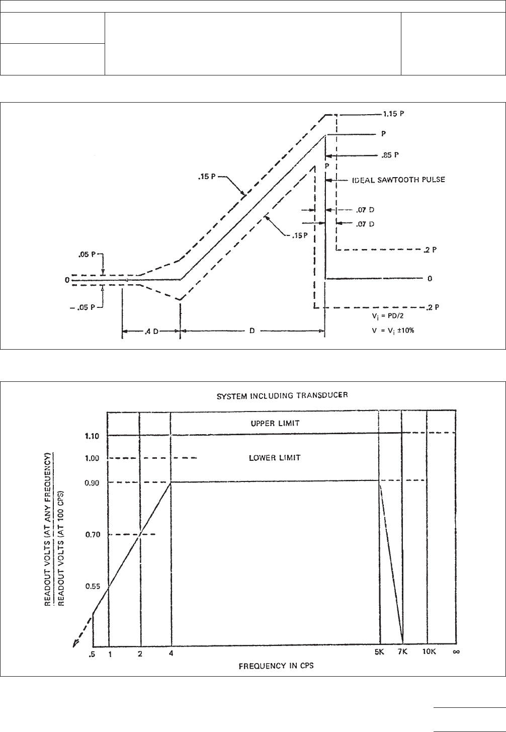
IPC-3-8-4
Figure 4 Tolerances for Terminal-Peak Sawtooth Shock Pulse
IPC-3-8-5
Figure 5 Tolerance Limits for Measuring System Frequency Response
IPC-TM-650
Number
3.8
Subject
Mechanical Shock, Connectors
Date
7/75
Revision
A
Page5of5

1.0 Scope
1.1
To determine the effects of a controlled salt laden atmo-
sphere on connector components, finishes and mechanisms.
This test is intended to explore the corrosion resisting proper-
ties of various materials and finishes and not to simulate cli-
matic conditions of a seacoast or shipboard environment.
2.0 Reference Documents
2.1
Information in this section is intended to parallel the test
method described in EIA-RS-364/TP-26.
3.0 Test Specimen
3.1
A connector (plug and receptacle) complete with appli-
cable guide, keying, and engaging hardware or a card-edge
receptacle and mating printed circuit board (if required by the
individual connector specification). The connector or recep-
tacle shall be mated unless otherwise specified in the indi-
vidual connector specification.
3.2 Neither the plug nor receptacle shall be mounted or ter-
minated during this test, unless such mounting (or termination)
is necessary (1) to insure the mechanical integrity of the com-
ponent, (2) to measure the specified electrical characteristic(s),
(3) was a requirement of previously imposed environmental or
functional tests.
3.3 Printed circuit boards and electrical connections to the
test specimen, except those connections considered under
test, may be coated with a suitable wax to inhibit corrosion.
The coating shall not be applied to any termination or portion
of the connector under test.
3.4 The plug, receptacle, or mated connector shall be sus-
pended or supported within the test chamber in a normal (or
typical) mounting attitude using non-corrosive material (e.g.,
plastic rods, hooks, waxed string, etc.). The test specimens
shall be positioned so that they do not shield each other from
the freely settling fog, and so that corrosion products and
condensate from one specimen do not fall upon another.
4.0 Apparatus
4.1
A chamber capable of maintaining a dry bulb tempera-
ture of +35°C (+1.1, -1.7°C) within the exposure zone. Satis-
factory methods for controlling the temperature are: (1) hous-
ing the chamber in a properly controlled constant-
temperature room; (2) insulating the chamber and pre-heating
the air to the proper temperature prior to atomization; (3) jack-
eting the chamber and controlling the temperature of the
water or air within the jacket.
NOTE:
The use of immersion heaters within the exposure
zone to maintain temperature is prohibited.
The chamber and all accessories exposed to the salt fog
atmosphere shall be constructed of non-reactive material
(e.g., glass, hard rubber, plastic, or wood other than ply-
wood). The exposure zone shall be vented to prevent a pres-
sure build-up affecting test conditions.
4.2 A compressed air supply free from all impurities such as
oil and dirt. Means shall be provided to humidify and warm the
compressed air as required to meet the operating conditions.
The air pressure shall be suitable to produce a finely divided
dense fog with the atomizer(s) used. To insure against clog-
ging of the atomizer(s) by salt deposition, the air should have
a relative humidity at the point of release from the nozzle
greater than 85 percent for the 20 percent solution and
greater than 95 percent for the 5 percent solution. A satisfac-
tory method of humidification is to pass the air in very fine
bubbles through a tower containing heated water. The tem-
perature of the water should be 35°C or higher, as necessi-
tated by increasing volume of air flow or increasing heat loss
through the chamber walls; it should not exceed a value
above which an excess of moisture is introduced into the
chamber or a value which makes it impossible to maintain the
operating temperature.
4.3 Atomizer(s) capable of an approximate atomization rate
of 3 quarts of salt solution per 10 cubic feet of exposure zone
volume per 24-hour period of test. The atomization and dis-
persion shall be such that a suitable receptacle at any point in
the exposure zone will collect 0.5 to 3.0 milliliters of solution
per hour for each 80 square centimeters of horizontal collect-
ing area (10 centimeters diameter) based on a minimum col-
lection period of 16 hours. The specific gravity of collected
solution shall meet the specified requirements of paragraph
4.4.
2215 Sanders Road
Northbrook, IL 60062-6135
IPC-TM-650
TEST METHODS MANUAL
Number
3.9
Subject
Salt Spray, Connectors
Date
7/75
Revision
A
Originating Task Group
N/A
Material in this Test Methods Manual was voluntarily established by Technical Committees of the IPC. This material is advisory only
and its use or adaptation is entirely voluntary. IPC disclaims all liability of any kind as to the use, application, or adaptation of this
material. Users are also wholly responsible for protecting themselves against all claims or liabilities for patent infringement.
Equipment referenced is for the convenience of the user and does not imply endorsement by the IPC.
Page1of2
ASSOCIATION CONNECTING
ELECTRONICS INDUSTRIES