IPC-TM-650 EN 2022 试验方法.pdf - 第75页
1 Scope This test method is used to establish and define the procedures for determining thermal gradient dimensional changes of a plastic dielectric, metal clad or unclad. This method may also be used to determine dimens…

1.0
Scope
This
method is intended to describe optically
enhanced measurement techniques for dimensions of 3 mm
or less, typically referenced on a Printed Board drawing. This
method will not cover mechanical dimensional verification
which is covered by IPC-TM-650, Method 2.2.1. This method
is intended to supersede IPC-TM-650, Method 2.2.3.
2.0
Applicable Documents
IPC-OI-645
Standard
for Visual Optical Inspection Aids
IPC-A-600E
Acceptability
of Printed Boards
3.0
Test Specimens
3.1
The
test specimen(s) shall be defined in the applicable
performance specification or standard.
4.0
Apparatus or Material
4.1
Optical
inspection aid capable of a magnification where
the feature(s) to be measured occupies at least 20% of the
field of view. (See IPC-OI-645 for detailed description.)
4.2
Reticle
or Filar Micrometer attachment to Optical Inspec-
tion Aid that contains gradiations or a scale, which will provide
a minimum measurement resolution of 50% of the last signifi-
cant digit of the referenced dimensional requirement. The
Reticle or Filar Micrometer should be calibrated at the given
magnification to ascertain the distance in mm (inches)
between each division.
5.0
Procedure
5.1
Select
an optical aid which allows for clear viewing of the
area(s) containing the attributes to be measured.
5.2
Adjust
the optical aid so that both the feature(s) to be
measured and the reticle or filar micrometer attachment are in
focus.
5.3 Align
the reticle or filar micrometer so that the measure-
ment scale is visible and aligned with the edges of the fea-
ture(s) to be measured.
5.4 Read
the reticle or filar micrometer to obtain the number
of divisions between feature edges.
5.5
To
obtain the actual dimensions of the feature, multiply
the number of divisions read by the calibration data previously
obtained for the reticle or filar micrometer in (µm/division)
(inches/division) at the given magnification.
5.6
Record
the dimensions for the attribute(s) measured
using the same number of significant digits specified by the
drawing, standard, or specification as a minimum or maximum
limiting value.
6.0 Notes
6.1
For
a thorough description of the requirements, defini-
tions, and certification provisions for optical inspection aids,
see IPC-OI-645.
6.2
IPC-A-600
contains figures and diagrams which depict
measurement techniques for certain attributed.
The
Institute for Interconnecting and Packaging Electronic Circuits
2215 Sanders Road • Northbrook, IL 60062
IPC-TM-650
TEST
METHODS MANUAL
Number
2.2.2
Subject
Optical
Dimensional Verification
Date
8/97
Revision
B
Originating Task Group
Rigid Board T.M. Task Group, 7-11d
Material
in this Test Methods Manual was voluntarily established by Technical Committees of the IPC. This material is advisory only
and its use or adaptation is entirely voluntary. IPC disclaims all liability of any kind as to the use, application, or adaptation of this
material. Users are also wholly responsible for protecting themselves against all claims or liabilities for patent infringement.
Equipment referenced is for the convenience of the user and does not imply endorsement by the IPC.
P
age1of1
电子技术应用 www.ChinaAET.com
1
Scope
This
test method is used to establish and define
the procedures for determining thermal gradient dimensional
changes of a plastic dielectric, metal clad or unclad.
This method may also be used to determine dimensional
changes after metal removal of a clad.
2
Applicable Documents
None
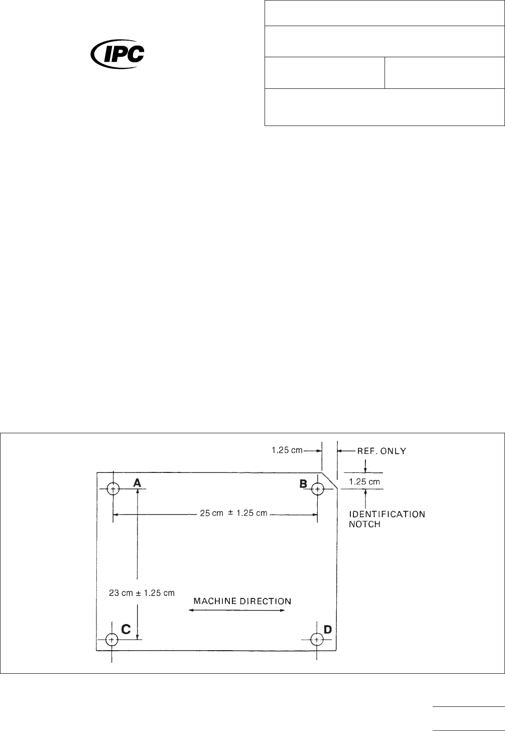
3
Test Specimen
The
test specimen shall be at least 27
cm x 29 cm of unclad or metal clad dielectric material cut and
punched per Figure 1.
4
Test Equipment
• Shear —
for cutting 27 cm x 29 cm test specimens.
• Micro-Rule — with dial indicator reading to 0.0125 mm or
less or an equivalent optical system.
• Hole Punch — 0.889 mm minimum diameter.
• Oven — mechanical convection type capable of maintaining
a temperature of 150°C ± 2°C.
• Etcher — capable of maintaining test specimens a 43°C ±
5°C during the metal removal.
• Line Scribe — capable of producing a line 0.125 mm wide
maximum.
• Chemical Etchant — capable of metal removal without det-
rimental effect to either the adhesive or dielectric.
5
Procedure
5.1 Sample Preparation
Scribe
0.125 mm wide lines or
punch holes at positions A through D in specimen at locations
shown in Figure 1.
Allow specimen to stabilize at 23°C ± 2°C and 50% ± 5%
relative humidity (RH) and measure separation of holes/lines
between corresponding positions (center of hole or center of
line). For example, the distance between hole centers A-B and
C-D, also A-C and B-D. Record as initial measurement (1).
Stabilization times may be reduced if statistically sound evi-
dence has been generated on the specific product line to
support shorter stabilization times to reach equilibrium.
IPC-224-1
Figure
1 Dimensional Stability Test Pattern
The
Institute for Interconnecting and Packaging Electronic Circuits
2215 Sanders Road • Northbrook, IL 60062
IPC-TM-650
TEST
METHODS MANUAL
Number
2.2.4
Subject
Dimensional
Stability, Flexible Dielectric Materials
Date
5/98
Revision
C
Originating Task Group
Flex Peel Strength Test Methods Task
Group (D-13A)
Material
in this Test Methods Manual was voluntarily established by Technical Committees of the IPC. This material is advisory only
and its use or adaptation is entirely voluntary. IPC disclaims all liability of any kind as to the use, application, or adaptation of this
material. Users are also wholly responsible for protecting themselves against all claims or liabilities for patent infringement.
Equipment referenced is for the convenience of the user and does not imply endorsement by the IPC.
P
age1of2
电子技术应用 www.ChinaAET.com

Twenty-four
hour stabilization is referee method.
5.2
Method A
Dimensional
stability of unclad material due
to thermal exposure—standard condition.
(1) Place test specimen unconstrained in an oven maintained
at 150°C ± 2°C for 30 ± 2 minutes.
(2) Cool specimen to standard conditions of 23°C ± 2°C and
50% ± 5% RH for 24 hours minimum (see 5).
(3) Remeasure separation of holes/lines and record as final
measurement after thermal exposure (F
l
).
5.3
Method B
Dimensional
stability of metal clad dielectrics
due to metal removal.
(1) Chemically erode the metal away except for the target
areas, which can have up to 13 mm x 13 mm square metal,
using an etchant that has no detrimental effect on either the
dielectric or adhesive. Wash and dry. The test specimen
should be unconstrained during the etching, washing, and
drying operation.
(2) Stabilize test specimen for 24 hours at 23°C ± 2°C and
50% ± 5% RH (see 5.1).
(3) Remeasure separation of holes/lines and record as final
measurement after etching (F
2
).
5.4
Method C
Dimensional
stability of dielectric due to
thermal exposure and metal removal, using specimens from
Method B.
(1) Place unconstrained etched, conditioned, and measured
specimen from Method B in an oven maintained at 150°C ±
2°C for 30 ± 2 minutes.
(2) Stabilize specimen at 23°C ± 2°C and 50% ± 5% RH for
24 hours and remeasure separation of holes (see 5.1).
(3) Remeasure separation of holes/lines and record as final
after etching and thermal exposure (F
3
).
5.5
Calculate
the linear dimensional changes as follows:
(Start with initial reading (I) from 5.1)
M.D. =
(A−B)
F
−(A−B)
I
(A−B)
I
+
(C−D)
F
−(C−D)
I
(C−D)
I
2
x
100
T.D. =
(A−C)
F
−(A−C)
I
(A−C)
I
+
(B−D)
F
−(B−D)
I
(B−D)
I
2
x
100
Where:
M.D. = % change in machine dimension.
T.D. = % change in transverse dimension.
I = Initial Reading.
F = Final Reading (Either F
1
,F
2
,o
rF
3
).
A-B
= Distance Between PointsA&B.
A-C = Distance Between PointsA&C.
C-D = Distance Between PointsC&D.
B-D = Distance Between PointsB&D.
6 Notes
The
alternate method for marking clad samples
allows the use of scribed lines. Caution must be used to pro-
tect scribed lines during etch operation.
IPC-TM-650
Number
2.2.4
Subject
Dimensional
Stability, Flexible Dielectric Materials
Date
5/98
Revision
C
P
age2of2
电子技术应用 www.ChinaAET.com