IPC-TM-650 EN 2022 试验方法.pdf - 第778页
1.0 Scope 1.1 To evaluate the contact resistance of electrical contacts at rated current. 2.0 Reference Documents 2.1 Information in this section is intended to parallel the test method described in EIA-RS-364/TP-06. 3.0…

the sample/coupon weight shall be recorded to the near-
est 0.0001 g. Note that the sample/coupon weight will not
settle completely.
These measurements characterize the bulk moisture content
of the test samples. If the moisture absorption rate is desired,
continue with process steps 3 through 5:
3. Measure and record ambient temperature and relative
humidity at the analytical balance measurement station.
4. The test sample/coupons shall remain at the analytical
balance measurement station for 15 minutes +1/-0 min-
utes and procedure steps 2-3 shall be repeated.
5. Repeat step 4, taking measurements at 15 minute inter-
vals, for at least 4 hours.
Note: The ambient temperature and humidity, the frequency
with which ambient conditions are recorded, the measure-
ment intervals between weighings and the number of weigh-
ings may be adjusted AABUS.
5.4 Calculations Calculate the bulk moisture content using
the following equation:
Moisture Content (%)=
(
(Initial Weight)−(Post−Bake Weight)
(Post−Bake Weight)
)
X 100
Calculate the moisture absorption rate by plotting the bulk
moisture content versus time using the data recorded in Pro-
cedure steps 3 through 5 of 5.3.
Note: Metals do not absorb moisture, and metal content in
the specimen will affect the accuracy of this determination. If
copper or other metals are likely to exceed 20% of the weight
of the specimen, this weight should be determined or esti-
mated, and subtracted from both the Initial Weight and the
Post-Bake Weight in the formula above. This correction factor
shall be AABUS.
5.5 Report Report the bulk moisture content or moisture
absorption rate for the sample/coupon.
IPC-TM-650
Number
2.6.28
Subject
Moisture Content and/or Moisture Absorption Rate, (Bulk)
Printed Board
Date
08/2010
Revision
Page2of2
1.0 Scope
1.1
To evaluate the contact resistance of electrical contacts
at rated current.
2.0 Reference Documents
2.1
Information in this section is intended to parallel the test
method described in EIA-RS-364/TP-06.
3.0 Test Specimen
3.1
The mated contacts of a connector mounted and, when
required, terminated in its normal manner or a mated pair of
individual contacts.
NOTE:
When mated contact pairs, not requiring housings,
are tested, they shall be rigidly mounted in a fixture to provide
mechanical stability and to insure proper mating and orienta-
tion.
3.2 For contacts having a wire-hole, crimp or other termina-
tion, a 3-foot length of continuous wire may be used for heat
dissipation. The wire size shall be specified in the individual
contact or connector specification.
3.3 Voltage connections may be attached permanently by
soldering, crimping, or other suitable method.
3.4 Unless otherwise specified in the individual contact or
connector specification, the test sample shall not be cleaned
by any means prior to the test nor shall any lubricants or other
coatings be applied.
4.0 Apparatus
4.1 Voltmeter (10000 ohms per volt or greater)
The
meter accuracy shall be such that the voltage value is mea-
sured accurately within 5 percent.
4.2 Ammeter The meter accuracy shall be such that the
current value is measured accurately within 5 percent.
4.3 Power supply capable of delivering the required test cur-
rent.
5.0 Procedure
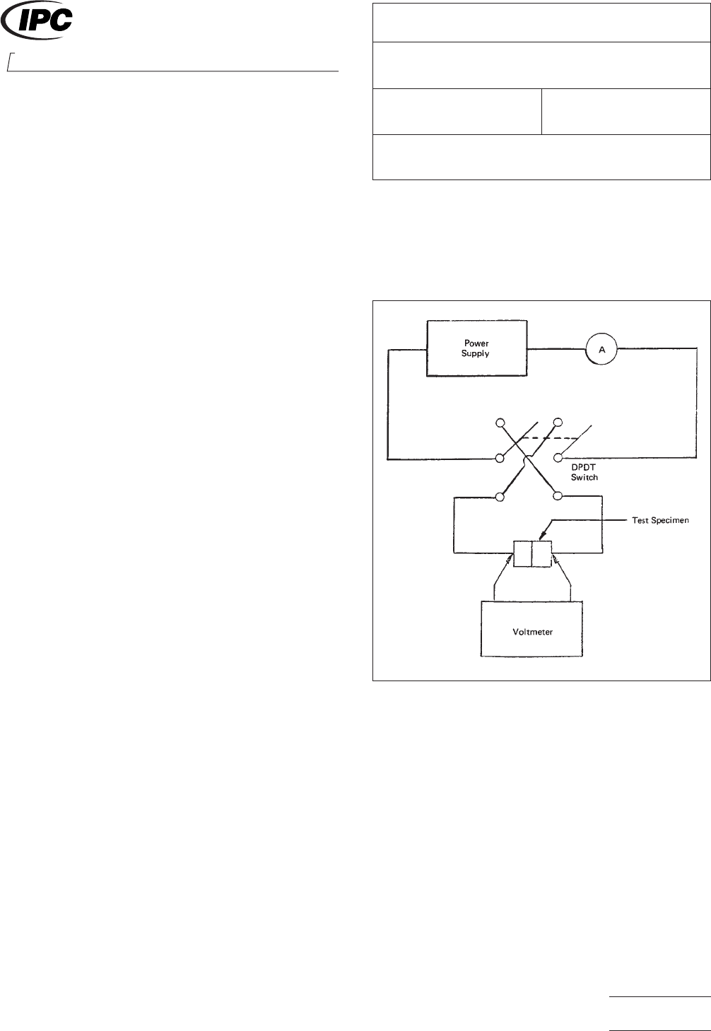
5.1
The contact resistance test shall be conducted using a
circuit as shown in Figure 1.
5.2 The current through the test sample shall be increased
to the value specified in the individual contact or connector
specification and shall be maintained until temperature stabili-
zation of the test sample at that current is attained. Tempera-
ture stability may be indicated by voltage drop stability.
5.3 The voltage drop across each pair of mated contacts
shall be measured with the voltmeter probes (or permanent
connection) positioned as follows:
A. Wire-Hole — On the contact with 1/8 inch of insulator.
B. Wrap-Post — On the wrap-post adjacent to the outer turn
of wire.
C. Crimp — On the wire (piercing the insulation) within 1/8
inch of insulator.
IPC-3-1-1
Figure 1 Test Set-up
2215 Sanders Road
Northbrook, IL 60062-6135
IPC-TM-650
TEST METHODS MANUAL
Number
3.1
Subject
Contact Resistance, Connectors
Date
7/75
Revision
A
Originating Task Group
N/A
Material in this Test Methods Manual was voluntarily established by Technical Committees of the IPC. This material is advisory only
and its use or adaptation is entirely voluntary. IPC disclaims all liability of any kind as to the use, application, or adaptation of this
material. Users are also wholly responsible for protecting themselves against all claims or liabilities for patent infringement.
Equipment referenced is for the convenience of the user and does not imply endorsement by the IPC.
Page1of2
ASSOCIATION CONNECTING
ELECTRONICS INDUSTRIES

D. Solder Tab — On the printed wiring traces as close to the
termination as practicable.
E. Press-Fit — On the pad of the plated-through hole as
close to the termination as practicable.
If the pad of the printed wiring board constitutes one-half of
the mated contact pair, the voltmeter probe shall be posi-
tioned on the pad immediately adjacent to, but not touching,
the mating contact (not inside the insulator).
NOTE:
In case of an environment resistant (sealed) connec-
tor, the voltmeter probes shall be positioned as close to the
sealing grommets as practicable.
5.4 The contact resistance shall be calculated by dividing
the voltage drop reading by the current reading. The value
thus obtained for each contact shall not exceed the maximum
allowable contact resistance as defined in the individual con-
tact or connector specification.
5.5 For voltage drops less than 1.0 millivolt, the voltage drop
across each pair of mated contacts with the current succes-
sively in both directions through the test specimen shall be
measured. The contact resistance shall be calculated, in each
the forward and reverse directions, by dividing the voltage
drop reading by the current reading. The average of the two
resistance values thus obtained for each contact shall not
exceed the maximum allowable contact resistance as defined
in the individual contact for connector specification.
6.0 Notes
6.1
Acceptance criteria shall be established as the maxi-
mum level at which stable electrical contact is maintained.
This resistance is an inherent characteristic of any given con-
nector contact design and is (when the connector is properly
applied) well below that resistance level required for circuit
function.
IPC-TM-650
Number
3.1
Subject
Contact Resistance, Connectors
Date
7/75
Revision
A
Page2of2