IPC-TM-650 EN 2022 试验方法.pdf - 第611页
divide the result by 10 (distance/time magnifier set at 10) to get the total T D of the test specimen. Subtract 0.20 ns x 2 = 0.40 ns delay caused by the connection device used at each end of the test cable and divide th…
4.4
Fixture
of plexiglass or other nonmetallic material. Cable
hangers to suspend the cable in air (see Figure 2)
5
Procedure
5.1
Allow
a minimum of one hour for TDR warmup and cali-
brate the instrument per manufacturer’s instructions.
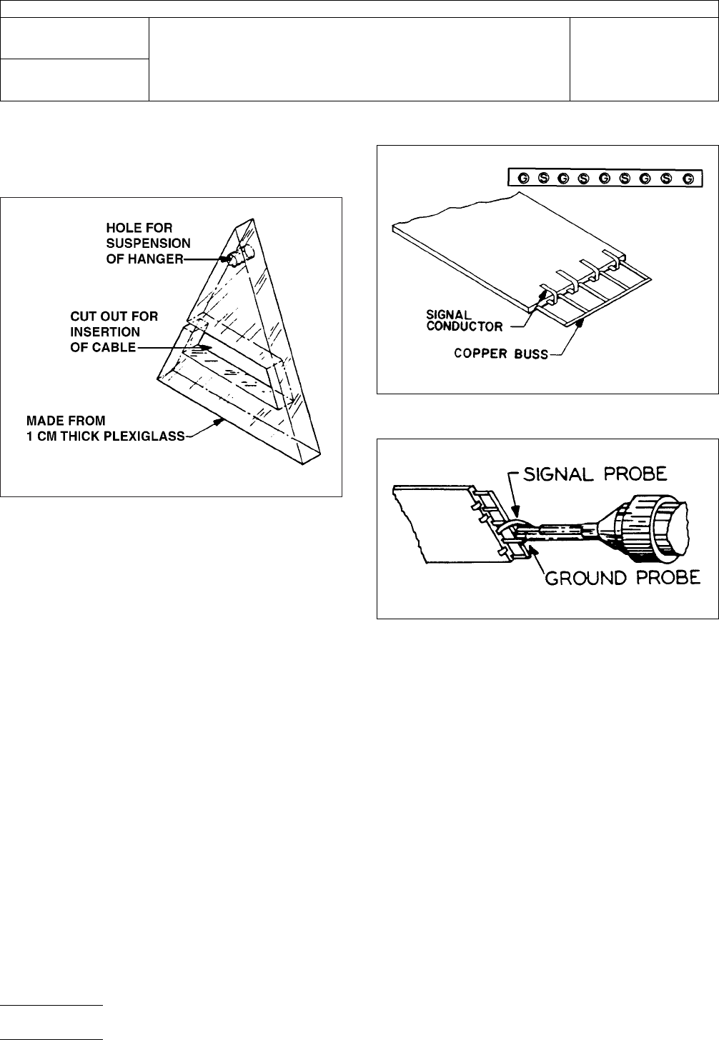
5.2
Prepare
the test specimen by stripping approximately 13
mm of insulation from both ends of the cable. Separate the
ground and signal conductors and solder a copper buss
across the grounds of each end (see Figure 3). Solder a stan-
dard cable connection device to each end of the cable (see
Figure 4).
5.3
Adjust
the TDR settings as follows: Vertical-0.2 p/cm;
Distanceltime-20 ns/cm; Magnifier-10X. (For equipment other
than Hewlett-Packard, use settings as close as possible to
these.)
5.4
Terminate
TDR output using the 509 load.
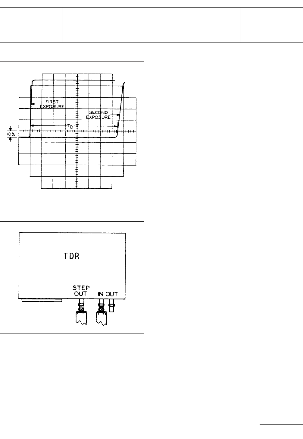
5.5
Adjust
the magnitude delay dial so the 50Ω termination
is visible and positioned to the left on the screen. Adjust the
vertical position so the pulse trace leading edge crosses the
horizontal graticule center line at 10% of pulse height (see
Figure 5). Mark the position of the leading edge of the pulse
on the horizontal graticule (mentally or by camera). If a cam-
era is used, don’t advance the film; a second exposure will be
made in 5.8.
5.6 Remove
the U section of coaxial GR connectors con-
necting the step out and signal in. Position each L connector
(made from the U connector) in the ‘‘STEP OUT’’ and ‘‘SIG-
NAL IN’’ connectors.
5.7
Connect
the test specimen, one end to the ‘‘Step Out’’
and the other end to ‘‘Signal In’’ (see Figure 6).
5.8
The
trace on the TDR screen will have moved to the
right from its original position in 5.5. Mark the position of the
leading edge of the pulse on the horizontal graticule (again at
10% of pulse height). At this time, a second exposure on the
same film used in 5.5 can be made. This will result in both
traces on one film. The distance between this mark and the
mark in 5.5 is the measured propagation delay (TD). Multiply
the measured T
D
by
20 (distance/time set at 20 ns/cm), then
IPC-2-5-19-1-4
Figure
2 Sample Hanging Device
IPC-2-5-19-2
Figure
3 Cable Preparation
IPC-2-5-19-3
Figure
4 Cable Connection
IPC-TM-650
Number
2.5.19
Subject
Propagation
Delay of Flat Cables Using Time Domain
Reflectometer
Date
7/84
Revision
A
P
age2of3
电子技术应用 www.ChinaAET.com
divide
the result by 10 (distance/time magnifier set at 10) to
get the total T
D
of
the test specimen. Subtract 0.20 ns x 2 =
0.40 ns delay caused by the connection device used at each
end of the test cable and divide this result by the exact length
of the test specimen to get the propagation delay in ns/0.3 m.
IPC-2-5-19-4
Figure
5 Dual Exposure Picture TDR Trace
IPC-2-5-19-6
Figure
6 Test Cable Hookup
IPC-TM-650
Number
2.5.19
Subject
Propagation
Delay of Flat Cables Using Time Domain
Reflectometer
Date
7/84
Revision
A
P
age3of3
电子技术应用 www.ChinaAET.com
1
Scope
This
test method describes the test procedures
required to measure propagation delay in flat cables. This test
method is an alternative to IPC-TM-650, Method 2.5.19.
Propagation delay is defined as the time required for a pulse
to traverse a unit length of cable. Excessive propagation delay
will result in the malfunction of critical circuits due to the late
arrival of pulses. Propagation delay is directly proportional to
the effective dielectric constant of the insulation.
2
Applicable Documents
IPC-TM-650
Test
Methods Manual
2.5.19 Propagation Delay of Flat Cables Using Time
Domain Reflectometer (TDR)
3
Test Specimen
3.1
One
pre-production or production sample 0.9 m to 3 m
long. The number of test samples should be determined by
the manufacturer and/or user.
4
Equipment/Apparatus
4.1
Oscilloscope:
Tektronix 7623 with a 7B53A dual time
base, or equivalent.The oscilloscope is dual time based, trig-
gered by the pulse generator, and capable of accuracy to 5
ns/div.
4.2
Pulse
generator: Tektronix PG501, Hewlett-Packard
8013B, or equivalent. The pulse characteristics from the pulse
generator should be determined by the manufacturer and/or
user.
4.3
Oscilloscope
test probes, preferably high speed, with
matched propagation delay
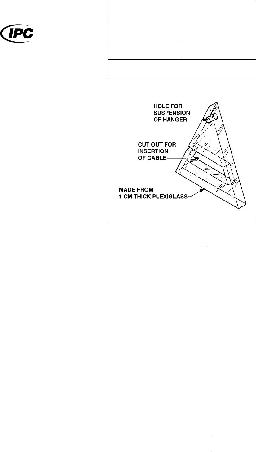
4.4
Cable
holder: Fixture of plexiglass or other nonmetallic
material
4.5
Cable
hangers to suspend the cable in air (see Figure 1)
4.6
A
termination resistor equal to the characteristic imped-
ance of the test specimen is required to terminate the output
end of the cable. When oscilloscope probes are attached to
the cable, the termination resistance (RT) has to be calculated:
R
T
=
R
PROBE
+ Z
oCABLE
R
PROBE
−Z
oCABLE
4.7
An
input resistor is required in series between the pulse
generator and the test specimen (only) when the characteris-
tic impedance of the cable is equal to or less than the output
impedance of the pulse generator. In this case:
Input Resistance = Z
oGENERATOR
–Z
oCABLE
4.8 Standard
cable connection device matching Figure 2. It
is made from a General Radio cable connector type 874-
C62A (propagation delay 0.2 ns).
4.9
A5
0Ω General Radio to BNC female adaptor is required
to connect the pulse generator to the test specimen.
5
Procedure
5.1
Allow
one hour for the test equipment to warm up. Con-
nect the pulse generator Trig output to the oscilloscope main
Trig in. Set the pulse generator output pulse characteristics as
specified for the test. Hook up both test probes from each
oscilloscope input to the single pulse generator output. Adjust
the scope sweep rate to 5 ns/div and view both channels.
IPC-2-5-19-1-4
Figure
1 Sample Cable Hanger
The
Institute for Interconnecting and Packaging Electronic Circuits
2215 Sanders Road • Northbrook, IL 60062
IPC-TM-650
TEST
METHODS MANUAL
Number
2.5.19.1
Subject
Propagation
Delay of Flat Cables Using Dual Trace
Oscilloscope
Date
7/84
Revision
A
Originating Task Group
Material
in this Test Methods Manual was voluntarily established by Technical Committees of the IPC. This material is advisory only
and its use or adaptation is entirely voluntary. IPC disclaims all liability of any kind as to the use, application, or adaptation of this
material. Users are also wholly responsible for protecting themselves against all claims or liabilities for patent infringement.
Equipment referenced is for the convenience of the user and does not imply endorsement by the IPC.
P
age1of4
电子技术应用 www.ChinaAET.com