IPC-TM-650 EN 2022 试验方法.pdf - 第336页
5.1.4 Process Sequence For a breakdown of time and temperature requirements of this test, see Table 1. 5.1.5 Apply tape to both the treated and non-treated sur- faces of the board using a wooden roller and fixed uniform …
1
Scope
This
test method shall establish and define the
methods for predicting the bond strength, on a go-no-go
basis, of additive rigid epoxy glass boards of the swell-
etchable type.
2
Applicable Documents
ASTM-D1000 Standard Test Method for Pressure-Sensitive
Adhesive-Coated Tapes Used for Electrical and Electronic
Applications
3 Test Specimen
A
minimum of two boards per test, each
board having the dimensions of 76 mm x 152 mm
4
Apparatus
4.1
Liter
beakers with slotted lids
4.2
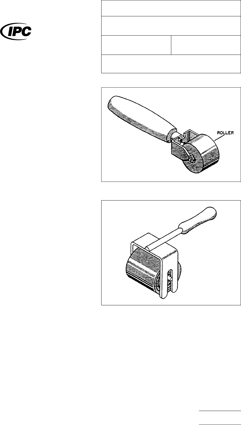
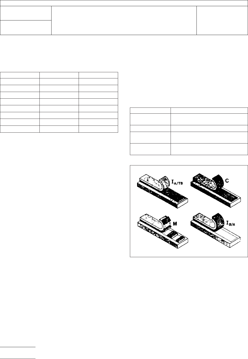
A
wooden wallpaper seam roller (see Figure 1 and Fig-
ure 2). The type in Figure 1 can be purchased in most hard-
ware shops, while the second roller is described in ASTM-
D100.
4.3
An
Instron or some other suitable peel tester, capable of
peeling at a 90° angle with a uniform, constant peel rate
4.4
3M
Brand Filament tape, No. 898, or equal. A 6.4 mm
width size is convenient.
4.5
Chemicals
An
additive chemical pre-treatment
sequence from any of the major electronic chemical suppliers
may be used. While the IPC does not endorse any specific
chemical supplier, the chemical sequence should consist of
several items.
• Conditioner
• Etchant
• Neutralizer
5
Procedure
5.1 Test
5.1.1
Prepare
the processing chemistry in one liter beakers
in accordance with the chemical suppliers’ recommendations.
5.1.2
In order to ensure that vapors from the processing
solution do not attack the resin, some precaution should be
taken to maintain minimum exposure of the untreated board
area to vapors (e.g., use of a slotted lid over beaker). Also, no
more than 10 sample boards/liter of any of the process
chemicals shall be processed.
5.1.3
Partially
submerge a board (76 mm x 152 mm) in liter
beakers following the process below. That portion of the
board, not in the liquid, provides an ‘‘as is’’ surface as a con-
trol and base comparison.
IPC-2-4-26-1
Figure
1 Paper Roller
IPC-2-4-26-2
Figure
2 Uniform Pressure Roller
The
Institute for Interconnecting and Packaging Electronic Circuits
2215 Sanders Road • Northbrook, IL 60062-6135
IPC-TM-650
TEST
METHODS MANUAL
Number
2.4.26
Subject
Tape
Test for Additive Printed Boards
Date
3/79
Revision
Originating Task Group
N/A
Material
in this Test Methods Manual was voluntarily established by Technical Committees of the IPC. This material is advisory only
and its use or adaptation is entirely voluntary. IPC disclaims all liability of any kind as to the use, application, or adaptation of this
material. Users are also wholly responsible for protecting themselves against all claims or liabilities for patent infringement.
Equipment referenced is for the convenience of the user and does not imply endorsement by the IPC.
P
age1of2
电子技术应用 www.ChinaAET.com
5.1.4
Process Sequence
For
a breakdown of time and
temperature requirements of this test, see Table 1.
5.1.5
Apply
tape to both the treated and non-treated sur-
faces of the board using a wooden roller and fixed uniform
pressure (approximately 4.5 kg.). Peel tape on Instron or other
peel tester at 900 angle and a 5 cm/min. peel rate. Report the
peel force as kg/cm on both treated and non-treated portions
board.
5.1.6 Use
two boards per test. Put tape on each side of the
board and obtain tape results for one tape strip per side per
board.
5.2
Evaluation
5.2.1
Report
the tape peel strength in kg/cm width.
5.2.2
Report
the locus of failure of peeled tape (see Note 1.).
Note 1: The requirement of specifying the locus of mode of
failure of the tape is very important and a critical aspect of the
test. In order to be consistent with descriptions of failure
modes, a common set of criteria is used, as defined in Table
2. Figure 3 shows, in schematic, the various failure modes one
could obtain during performing this test. The three layers, from
bottom to top, are (1) the epoxy/glass substrate, (2) the adhe-
sive component of the tape, and (3) the tape backing (see top
left drawing in Figure 3).
5.2.3 Report the average of the two tape peel strengths (in
kg/cm width) for the same side of both boards.
T
able 1 Process Sequence
T
emp (°C) Time (Min)
Conditioner
32 4
Rinse 16-27 2-3
Etch 66 6.5
Air Dry – 0.75
Triple Rinse 16-27 3-5
Neutralizer 52 2.5
Rinse 25 5
Air Dry 25 Overnight
Table 2 Modes of Failure Shown in Figure 3
Notation
Meaning of Failure Mode
I
A/-TB
Interfacial
failure, between adhesive
and tape backing
C Cohesive failure within tape adhesive
M Mixed failure mode, a combination of
the other types
I
B/A
Interfacial
failure, between the board
and the adhesive of the tape.
IPC-2-4-26-3
Figure
3 Modes of Failure
IPC-TM-650
Number
2.4.26
Subject
Tape
Test for Additive Printed Boards
Date
3/79
Revision
P
age2of2
电子技术应用 www.ChinaAET.com

1.0
Scope
This
method is designed to evaluate the resis-
tance of solder mask or conformally coated surfaces to rub-
bing abrasion.
2.0
Applicable Documents
None
3.0
Test Specimen
An
IPC Multipurpose Test Board,
Number IPC-B-25 or any preproduction or production board
10.8 cm x 10.8 cm [4
1
⁄
4
i
n.x4
1
⁄
4
in.]
in size and coated with
solder mask or conformal coating.
4.0
Apparatus
4.1
Taber
Abraser Model 5130
4.2
1000
gram load for each wheel
4.3
CS-10
Calibrase wheels
5.0
Procedure
5.1 Preparation
5.1.1
Drill
or punch hole in middle of specimen for mounting
specimen on Taber Abraser.
5.1.2
Mount
calibrase wheels and pressure load (1000
grams) on equipment.
5.1.3
Clean
calibrase wheels (CS-10) according to recom-
mended procedures in Taber Abraser Manual.
5.2
Test
Place
sample on abraser and test specimen to the
required number of cycles of abrasion.
5.3
Evaluation
Examine
the coated board for break-
through to the conductive pattern or base material.
6.0
Notes
Taber
Abraser Model 5130, available from Tele-
dyne Taber, 455 Bryant St., N. Tonawanda, NY 14120 or
Pacific Scientific, Gardner Neotech Division, 2431 Linden
Lane, Silver Springs, MD 20910 or equivalent.
The
Institute for Interconnecting and Packaging Electronic Circuits
2215 Sanders Road • Northbrook, IL 60062-6135
IPC-TM-650
TEST
METHODS MANUAL
Number
2.4.27.1
Subject
Abrasion
(Taber Method) Solder Mask and
Conformal Coating
Date
1/95
Revision
B
Originating Task Group
Conformal Coating Task Group (5-33a)
Material
in this Test Methods Manual was voluntarily established by Technical Committees of the IPC. This material is advisory only
and its use or adaptation is entirely voluntary. IPC disclaims all liability of any kind as to the use, application, or adaptation of this
material. Users are also wholly responsible for protecting themselves against all claims or liabilities for patent infringement.
Equipment referenced is for the convenience of the user and does not imply endorsement by the IPC.
P
age1of1
电子技术应用 www.ChinaAET.com